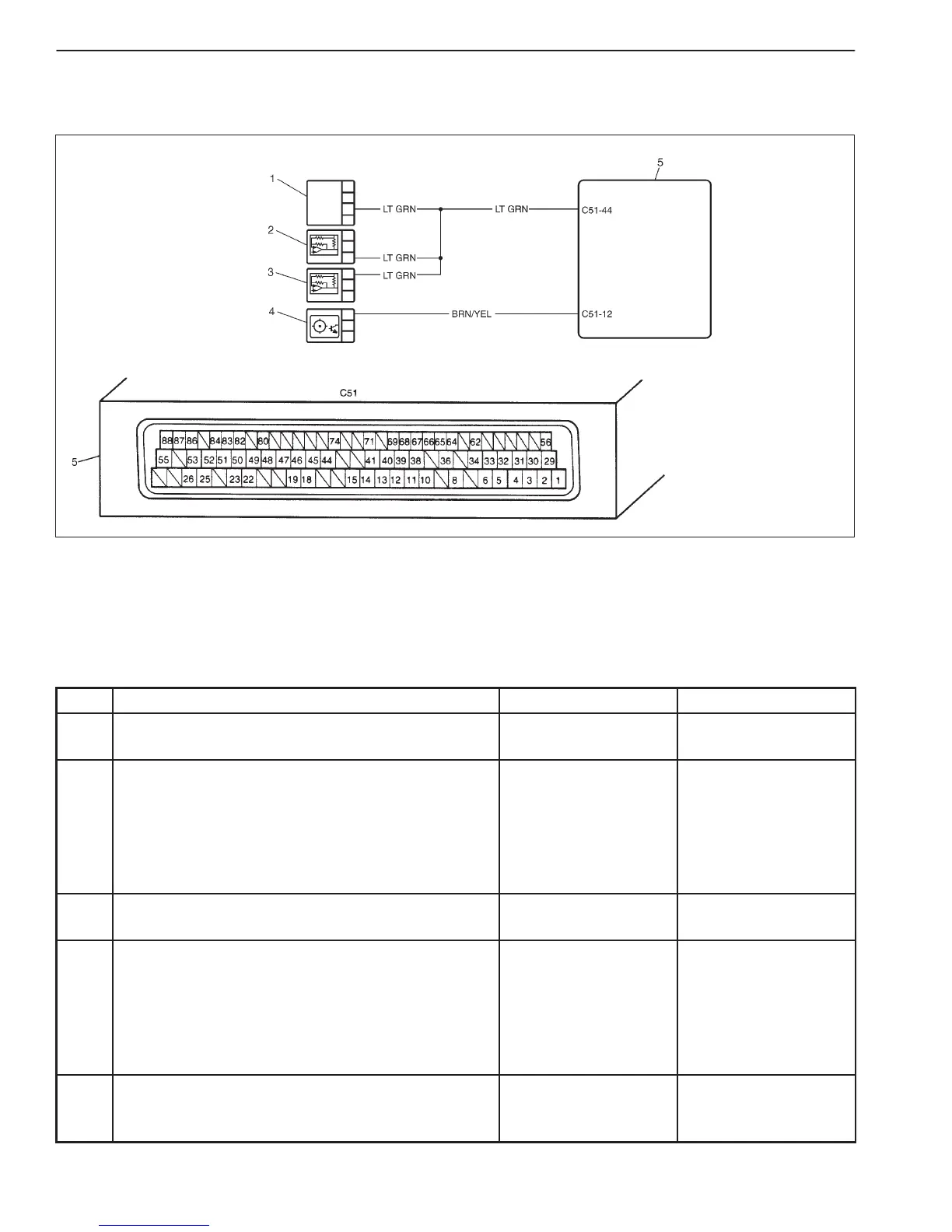
1. Throttle position sensor
2. Fuel pressure sensor
3. Intake air pressure sensor
4. Camshaft position sensor
5. ECM
6-66 ENGINE DIAGNOSIS (RHZ ENGINE WITH SINGLE-CONNECTOR ECM)
DTC P1614 (P0560) SENSOR SUPPLY FUNCTION
WIRING DIAGRAM
DTC CONFIRMATION PROCEDURE
1) Connect scan tool to DLC with ignition switch OFF.
2) Turn ON ignition switch and clear DTC, pending DTC and freeze flame data by using scan tool.
3) Check DTC and pending DTC by using scan tool.
TROUBLESHOOTING
STEP ACTION YES NO
1 Was “ENGINE DIAG. FLOW TABLE” performed? Go to Step 2. Go to “ENGINE DIAG.
FLOW TABLE”.
2 “LT GRN” Circuit Check
1) Disconnect connector at intake air pressure
sensor.
2) Check voltage between “LT GRN” wire terminal of
connector and ground with ignition switch ON.
Is it 5.1 V or more?
“LT GRN” wire short to
battery.
Go to Step 3.
3 Is it 4.88 V or less? “LT GRN” wire short to
ground.
Go to Step 4.
4 “BRN/YEL” Circuit Check
1) Disconnect connector at camshaft position
sensor.
2) Check voltage between “BRN/YEL” wire terminal
of connector and ground with ignition switch ON.
Is it 5.1 V or more?
“BRN/YEL” wire short
to battery.
Go to Step 5.
5 Is it 4.88 V or less? “BRN/YEL” wire short
to ground.
Substitute a known-
good ECM and
recheck.

 Loading...


