6-1-8 ENGINE DIAGNOSIS (RHZ ENGINE WITH TRIPLE-CONNECTOR ECM)
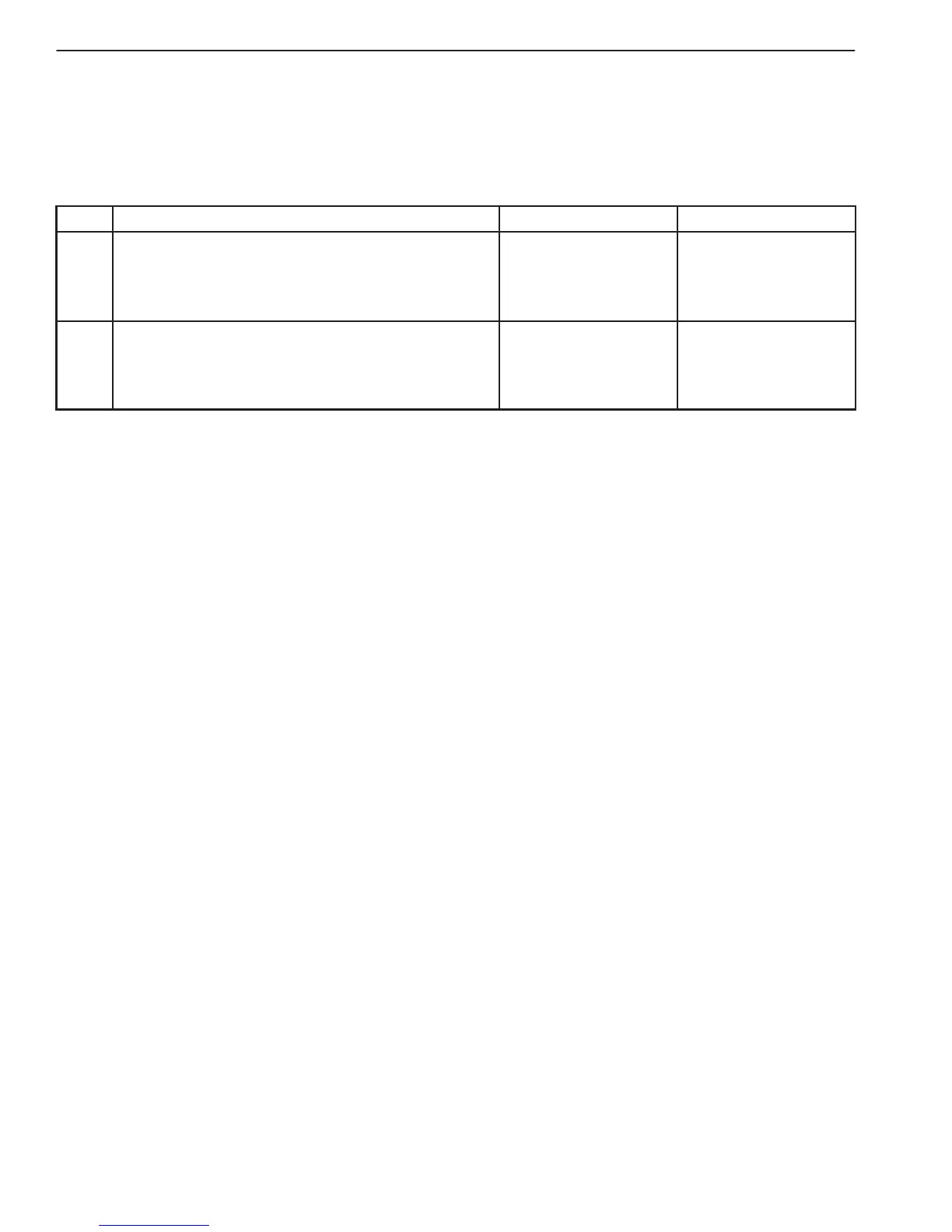
TABLE A-2 MALFUNCTION INDICATOR LAMP CIRCUIT CHECK – MIL REMAINS “ON”
AFTER ENGINE STARTS
WIRING DIAGRAM/CIRCUIT DESCRIPTION
Refer to TABLE A-1.
INSPECTION
STEP ACTION YES NO
1 DTC Check.
1) With ignition switch OFF, install scan tool.
2) Start engine and check DTC.
Is there any DTC(s).
Go to Step 2 of
“ENGINE DIAG.
FLOW TABLE” in
this section.
Go to Step 2.
2 MIL circuit Check:
(1) With ignition switch OFF, disconnect couplers
from ECM (PCM).
Does MIL turn ON at ignition switch ON?
“PPL/YEL” wire
shorted to ground
circuit.
Substitute a
known-good
ECM (PCM) and
recheck.
TABLE A-3 ECM (PCM) POWER AND GROUND CIRCUIT CHECK – MIL DOESN’T LIGHT AT
IGNITION SWITCH ON AND ENGINE DOESN’T START THOUGH IT IS CRANKED UP.
WIRING DIAGRAM
Refer to TABLE A-1.
CIRCUIT DESCRIPTION
When the ignition switch is turned ON, the double relay turns ON (the contact point closes) and the main power
is supplied to ECM (PCM).

 Loading...


