Home
Suzuki
Automobile
GRAND VITARA XL-7
Suzuki GRAND VITARA XL-7 Service Manual
5
of 1
of 1 rating
597 pages
Give review
Manual
Specs
To Next Page
To Next Page
To Previous Page
To Previous Page
Loading...
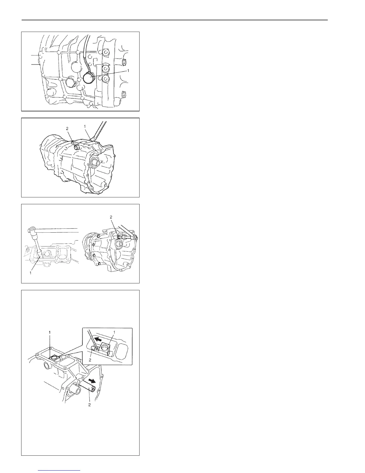
7A2-18
MANUAL TRANSMISSION
2)
Remove back-up light switch (1).
3)
Remove return spring low bolt (1) and return spring reverse bolt
(2).
4)
Remove gear shift shaft inner bolt (1) and plug (2).
5)
Using bolt hole, pull gear shift inner shaft (2) and then remove
gear shift shaft inner lever (1).
365
367
Table of Contents
Section 0A General Information
4
Default Chapter
4
Table of Contents
4
Precautions
5
General Precautions
5
Identification Information
8
Vehicle Identification Number
8
Engine Identification Number
8
Transmission Identification Number
8
Warning, Caution and Information Labels
9
Fastener Information
10
Metric Fasteners
10
Maintenance and Lubrication
11
Maintenance Schedule
12
Maintenance Recommended under Severe Driving Conditions
14
Fuel System
19
Chassis and Body
21
Recommended Fluids and Lubricants
23
Heater and Ventilation
24
General Description
25
Supplementary Heater
25
Diagnosis
25
Diagnosis Table
25
Wiring Circuit
26
Supplementary Heater System Operation
26
On-Vehicle Service
27
Supplementary Heater
27
Supplementary Heater Relay
27
Radiator Fan Signal Relay
28
Supplementary Heater Switch
28
Section 1B Air Conditioning (Optional)
30
General Description
31
Major Components and Location
31
Diagnosis
32
General
32
Wiring Circuit
34
Inspection of A/C Controller and Its Circuits
36
Compressor Drive Belt
40
On-Vehicle Service
41
Relays
41
Compressor Assembly
42
Required Service Material
43
Section 3B1 Power Steering (P/S) System
44
Diagnosis
45
Power Steering Pump Drive Belt
45
Fluid Leakage Check
45
Hydraulic Pressure in P/S Circuit Check
46
General Description
45
Power Steering (P/S) Pump Assembly
45
On-Vehicle Service
48
Power Steering Pump
48
Required Service Materials
50
Special Tools
50
Rear Suspension
51
Oil Seal
55
Drive Shaft
56
Propeller Shafts
59
Propeller Shaft
60
Tightening Torque Specifications
50
Section 6 Engine General Information and Diagnosis (Rhz Engine with Single-Connector Ecm)
61
General Information
63
Engine Diagnosis
66
On-Board Diagnostic System
66
Precaution in Diagnosing Trouble
69
Customer Problem Inspection Form
72
Diagnostic Trouble Code (DTC) Check
73
Diagnostic Trouble Code (DTC) Clearance
73
Malfunction Indicator Lamp (MIL) Check
73
Fail-Safe Table
74
Diagnostic Trouble Code (DTC) Table
75
Visual Inspection
78
Engine Basic Check
79
Engine Diagnosis Table
80
Inspection of PCM (ECM) and Its Circuits
85
Voltage Check
85
Resistance Check
87
Problem
93
DTC P0115 (DTC P0115) Engine
96
Malfunction
97
Monitoring System Malfunction
97
Problem
97
DTC P0180 Fuel Temp. Sensor Circuit Malfunction
99
DTC P0190 (P0190) Fuel Rail Pressure Sensor Circuit Malfunction
100
DTC P0191 (P0230) Fuel Rail
102
Consistency Function
102
DTC P1112 (P0230) Fuel Pressure Monitoring Circuit Malfunction
102
DTC P0243 (P0243) Turbo Pressure Solenoid Valve Circuit Range/Performance Problem
108
Turbo Pressure Solenoid Valve Circuit Range/Performance Problem
108
Relay Circuit Malfunction
111
DTC P0381 Glow Indicator Lamp Circuit Malfunction
112
DTC P0401 (P0903) EGR Solenoid Valve Flow Insufficient Defected
113
DTC P0402 (P0903) EGR Solenoid Valve Flow Excessive Detected
113
DTC P0403 (P0403) EGR Solenoid Valve Circuit Malfunction
114
DTC P1169 (P0170) Condenser Voltage Function 1
115
DTC P1170 (P0170) Condenser Voltage Function 2
115
DTC P1101 (P0105) Barometric Pressure Sensor Circuit Malfunction
115
DTC P1108 Radiator Fan High Speed Circuit Malfunction
116
DTC P1109 Radiator Fan Low Speed Circuit Malfunction
117
DTC P1110 A/C Signal Circuit Malfunction
118
DTC P1135 3Rd Piston Deactivator
119
DTC P1138 (P0230) Fuel Pressure Regulator Circuit Malfunction
120
DTC P1402 (P0510) Throttle Solenoid Valve Circuit Malfunction
121
DTC P1511 Ignition Switch Circuit Malfunction
122
DTC P1519 Radiator Fan Circuit Malfunction
123
DTC P1606 MIL Circuit Malfunction
124
DTC P1608 ECT Warning Lamp Circuit Malfunction
125
DTC P1614 (P0560) Sensor Supply Function
126
Section 6-1 Engine General Information and Diagnosis (Rhz Engine with Triple-Connector Ecm)
140
Default Chapter
141
DTC P0221 (P0220) TP Range/Performance Problem
141
Malfunction
141
DTC P0235 (P0235) Intake Air Pressure Sensor Circuit Malfunction
141
DTC P0340 (P0335/P0340) CMP Sensor Circuit Malfunction
141
DTC P0500 (P0500) Vehicle Speed Sensor Circuit Malfunction
141
DTC P0560 (P0560) Power Supply Circuit Malfunction
141
General Information
142
Engine Diagnosis
142
Engine Diagnostic Flow Table
142
Customer Problem Inspection Form
142
Diagnostic Trouble Code (DTC) Check
142
Diagnostic Trouble Code (DTC) Clearance
142
Malfunction Indicator Lamp (MIL) Check
142
Inspection of PCM (ECM) and Its Circuits
143
Voltage Check
143
Resistance Check
145
Ground Circuit Check
146
General Description
142
On-Board Diagnosis
142
Precaution in Diagnosing Trouble
142
DTC P0101 (P0100) MAF Sensor Circuit Range/Performance Problem
151
DTC P0115 (DTC P0115) Engine Coolant Temp. Sensor Circuit Malfunction
154
Monitoring System Malfunction
155
Problem
155
DTC P0180 Fuel Temp. Sensor Circuit Malfunction
157
DTC P0190 (P0190) Fuel Rail Pressure Sensor Circuit Malfunction
158
Consistency Function
160
DTC P1112 (P0230) Fuel Pressure Monitoring Circuit Malfunction
160
Dtc P0202 (P0200) Injector Circuit Malfunction Cylinder 2
162
Dtc P0203 (P0200) Injector Circuit Malfunction Cylinder 3
162
Dtc P0204 (P0200) Injector Circuit Malfunction Cylinder 4
162
DTC P0215 Double Relay Circuit Malfunction
164
DTC P0230 Fuel Pump Supply Circuit Malfunction
165
DTC P0243 (P0243) Turbo Pressure Solenoid Valve Circuit Range/Performance Problem
166
Relay Circuit Malfunction
169
DTC P0381 Glow Indicator Lamp Circuit Malfunction
170
DTC P0402 (P0903) EGR Solenoid Valve Flow Excessive Detected
171
DTC P0403 (P0403) EGR Solenoid Valve Circuit Malfunction
172
DTC P0561 Stabilization of Sensor Supply
173
DTC P0603/P0606!!G/P1171/P1617 ECM Function
173
DTC P1101 (P0105) Barometric Pressure Sensor Circuit Malfunction
173
Dtc P1169 (P0170) Condenser Voltage Function 1
173
Dtc P1170 (P0170) Condenser Voltage Function 2
173
DTC P1108 Radiator Fan High Speed Circuit Malfunction
174
DTC P1109 Radiator Fan Low Speed Circuit Malfunction
175
DTC P1110 A/C Signal Circuit Malfunction
176
DTC P1135 3Rd Piston Deactivator
177
DTC P1138 (P0230) Fuel Pressure Regulator Circuit Malfunction
178
DTC P1402 (P0510) Throttle Solenoid Valve Circuit Malfunction
179
DTC P1511 Ignition Switch Circuit Malfunction
180
DTC P1519 Radiator Fan Circuit Malfunction
181
DTC P1606 MIL Circuit Malfunction
182
DTC P1608 ECT Warning Lamp Circuit Malfunction
183
DTC P1614 (P0560) Sensor Supply Function
184
DTC P0500 (P0500) Vehicle Speed Sensor Circuit Malfunction
191
DTC P0235 (P0235) Intake Air Pressure Sensor Circuit Malfunction
193
DTC P0560 (P0560) Power Supply Circuit Malfunction
195
Inspection
196
Special Tools
198
Section 6A3 Engine Mechanical (Rhz Engine)
199
Default Chapter
199
Engine Mechanical
199
Maintenance
200
Oil Level Check, Oil Change and Oil Filter Change
200
On-Vehicle Service
200
Compression Check
200
Air Cleaner Element
201
Cylinder Head Cover
202
Intake Manifold
204
Exhaust Manifold
205
Timing Belt and Belt Tensioner (Engine with Camshaft Hub)
206
Timing Belt and Belt Tensioner (Engine Without Camshaft Hub)
212
Oil Pressure Switch
218
Oil Cooler
218
Oil Pan and Oil Pump Strainer
219
Oil Pump
224
Camshaft and Valve Lash Adjusters
228
Valves and Cylinder Head
230
Piston, Piston Rings, Connecting Rods and Cylinders
240
Unit Repair Overhaul
245
Engine Assembly
245
Main Bearings, Crankshaft and Cylinder Block
248
Special Tools
255
Required Service Materials
256
Section 6B Engine Cooling
258
Default Chapter
258
Engine Cooling
258
General Description
259
Cooling Fan
261
Diagnosis
262
Maintenance
263
Coolant Level
263
Cooling System Service
263
Cooling System Flush and Refill
264
On-Vehicle Service
266
Cooling System Draining
266
Cooling Water Pipes or Hoses
266
Thermostat
267
Radiator
268
Radiator Fan Relay
269
Water Pump
270
Required Service Materials
271
Engine Fuel
272
Fuel Tank
276
Fuel Level Gauge
278
Section 6E3 Engine and Emission Control System (Rhz Engine)
279
General Description
281
System Diagram
281
Air Intake System
282
Fuel Delivery System
283
Electronic Control System
284
System Location Diagram
284
System Wiring Diagram
285
On-Vehicle Service
289
Accelerator Cable Adjustment
289
Idle Speed Inspection
289
Air Intake System
290
Vacuum Hose Routing Diagram
290
Intercooler
291
Throttle Valve Assembly
292
EGR Throttle Solenoid Valve
293
Vacuum Pump
293
Turbocharger
294
Boost Pressure Regulator Solenoid Valve
296
Glow Plug
297
Fuel Delivery System
298
Precautions
298
Low Pressure Fuel Supply System
300
Fuel Pump
301
Fuel Heater
301
Fuel Injector
302
Common Rail
305
(High Pressure Fuel Injection Rail)
305
Injection Pump
308
Electronic Control System
310
Engine Control Module (ECM)
310
Mass Air Flow Sensor (MAF Sensor)
312
Throttle Position Sensor (TP Sensor)
313
(Accelerator Stroke Sensor)
313
Fuel Temperature Sensor Assembly
314
Fuel (Rail) Pressure Sensor
316
Engine Coolant Temperature Sensor (ECT Sensor)
317
Camshaft Position Sensor (CMP Sensor)
318
Vss
318
Crankshaft Position Sensor
319
(Engine Speed Sensor)
319
Absolute Pressure Sensor)
320
Radiator Fan Control System
321
Double Relay
324
Pre Post Heating Relay (Control Unit)
325
Egr System
326
Section 6G Cranking System (2.0 Kw Reduction Type)
330
General Description
331
Cranking Circuit
331
Starting Motor Circuit
331
Starting Motor
332
Diagnosis
333
Unit Repair Overhaul
334
Dismounting and Remounting
334
Disassembly and Reassembly
334
Inspection
335
Performance Test
338
Hold-In Test
338
No-Load Performance Test
338
Plunger and Pinion Return Test
338
Pull-In Test
338
Specifications
339
Required Service Material
339
Tightening Torque Specifications
339
Section 6H Charging System
340
Warning
341
On-Vehicle Service
341
Generator Belt
341
Unit Repair Overhaul
343
Generator
343
Dismounting and Remounting
343
Disassembly and Reassembly
344
Specifications
345
Generator
345
Special Tools
345
6H-6 Charging System
345
Exhaust System
346
Section 7A2 Manual Transmission
349
Default Chapter
349
Manual Transmission
349
General Description
350
Components
351
Diagnosis
352
Diagnosis Table
352
On-Vehicle Service
353
Gear Oil Inspection and Change
353
Shift Control Levers
354
Switches
356
Back up Light Switch Removal and Installation
356
Transfer 4Wd Switch Removal and Installation
356
4Wd Switch and Back up Light Switch Inspection
357
Engine Rear Mounting
358
Dismounting of Transmission Unit
358
Remounting of Transmission Unit
361
Unit Repair
362
Transmission Case Components
362
Input and Counter Shaft Components
363
Gear Shifter Components
364
Unit Disassembly
365
Gear Shift Lever Case Assembly
365
Transmission Unit
365
Input Shaft Assembly
374
Main Shaft Assembly
374
Counter Shaft Assembly
375
5Th and Reverse Synchronizer Ring
376
Input Shaft Bearing Retainer and Oil Seal
376
Transmission Rear Case
376
Components Inspection
377
Input Shaft Assembly
377
Main Shaft Assembly
378
Counter Shaft and Reverse Idle Gear
380
Unit Assembly
382
Gear Shift Lever Case Assembly
382
Input Shaft Assembly
383
Main Shaft Assembly
384
Counter Shaft Assembly
388
Input Shaft Bearing Retainer and Oil Seal
389
Transmission Rear Case
389
Transmission Intermediate Case and Front Case (Location of Knock and Plug)
390
Specification
390
Tightening Torque
390
Required Service Material
404
Special Tool
405
Section 7B1 Automatic Transmission (4 A/T)
406
General Description
408
Clutch/Brake Functions
410
Table of Component Operation
411
Operation of Shift Solenoids and Tcc Solenoid
414
Diagnosis
416
On-Board Diagnostic System
416
Precaution in Diagnosing Trouble
417
Automatic Transmission Diagnostic Flow Table
418
O/D Off" Lamp Check
421
Diagnostic Trouble Code (Dtc) Check
421
Diagnostic Trouble Code Clearance
423
Diagnostic Trouble Code Table
424
Fail Safe Table
425
Visual Inspection
426
A/T Basic Check
426
Trouble Diagnosis Table 1
428
Trouble Diagnosis Table 2
428
Trouble Diagnosis Table 3
428
Road Test
430
Manual Road Test
431
Engine Brake Test
432
Stall Test
432
Time Lag Test
434
Line Pressure Test
435
"P" Range Test
436
O/D
439
Inspection of Tcm and Its Circuits
441
Wire Harness and Connectors
441
Malfunction
442
Malfunction
447
Dtc P0715 Input/Turbine Speed Sensor Circuit Malfunction 7B1
447
Dtc P0720 Output Speed Sensor Circuit Malfunction 7B1
450
Dtc P0725 Engine Speed Input Circuit Malfunction 7B1
453
Dtc P0748 Pressure Control Solenoid Electrical 7B1
457
Electrical
459
Malfunction
461
Malfunction of Tcm
463
Dtc P1730 Engine Torque Signal Circuit Malfunction 7B1
464
Maintenance Service
466
Fluid Level
466
Fluid Change
467
On-Vehicle Service
466
Manual Selector Assembly
468
Oil Cooler Hoses
468
Select Cable
469
Transmission Range Switch
470
Input Shaft Speed Sensor
471
O/D off Switch
471
Output Shaft Speed Sensor
471
Solenoid Valves (Shift Solenoid Valves, Tcc Solenoid Valve and Pressure Control Solenoid Valve)
472
Solenoid
472
Solenoid Valves (Shift Solenoid Valves and Tcc Solenoid Valve)
472
Acceleration Stroke Sensor
475
Transmission Control Module (Tcm)
475
4Wd Low Switch
476
Oil Cooler Pipes
476
Automatic Transmission Assembly (with Transfer)
477
Unit Repair
482
Precautions
482
Part Inspection and Correction Table
483
Unit Disassembly
484
Sub-Assembly Repair
489
Overdrive (Case Side)
489
Forward Clutch
492
Direct Clutch
496
Center Support
499
Planetary Gears and Output Shaft
505
Valve Body Assembly
509
Unit Assembly
511
Bearing and Race Installation Diagram
521
Tightening Torque Specification
522
Required Service Material
523
Special Tool
523
Removal and Installation
543
Section 7F Differential (Rear)
548
General Description
549
Diagnosis
549
Diagnosis Table
549
On-Vehicle Service
550
Precaution for Maintenance Service
551
Differential Gear Oil Change
551
Rear Differential Assembly
552
Dismounting
552
Remounting
552
Unit Repair
553
Disassembling Unit
553
Component Inspection
556
Sub-Assembly Adjustment and Reassembly
556
Differential Carrier
556
Differential Case
557
Differential Side Bearing
559
Drive Bevel Pinion
560
Assembling Unit
565
Required Service Material
568
Tightening Torque Specification
568
Special Tool
569
Combination Meter
572
Section 8G Immobilizer Control System (if Equipped)
574
Default Chapter
574
Immobilizer Control System
574
General Description
575
Ignition Key
575
Coil Antenna
575
Immobilizer Control Module
575
Ecm
575
On-Board Diagnostic System
578
(Self-Diagnosis Function)
578
Diagnosis
579
Precautions in Diagnosing Troubles
579
Immobilizer Diagnostic Flow Table
580
Diagnostic Trouble Code (DTC) Check (Immobilizer Control Module)
581
Diagnostic Trouble Code Table
582
Control Module
584
DTC11 Transponder Code Not Matched
584
DTC31 Transponder Code Not Registered
584
DTC12 Fault in Immobilizer Control Module
584
DTC13 no Transponder Code Transmitted from Ignition Key
585
DTC14 Coil Antenna Circuit Malfunction
585
DTC41 ECM Not Registered
586
DTC42 Serial Data Circuit Malfunction
587
DTC43 ECU Code Not Matched
588
Inspection of Immobilizer Control Module and Its Circuit
589
Voltage Check
589
Resistance Check
590
On-Vehicle Service
591
Precautions in Handling Immobilizer Control System
591
Immobilizer Control Module
592
Coil Antenna
592
How to Register Ignition Key
593
Procedure after Immobilizer Control Module Replacement
594
Procedure after Ecm Replacement
595
Special Tools
596
Other manuals for Suzuki GRAND VITARA XL-7
Owner's Manual
656 pages
5
Based on 1 rating
Ask a question
Give review
Questions and Answers:
Need help?
Do you have a question about the Suzuki GRAND VITARA XL-7 and is the answer not in the manual?
Ask a question
Suzuki GRAND VITARA XL-7 Specifications
General
Brand
Suzuki
Model
GRAND VITARA XL-7
Category
Automobile
Language
English
Related product manuals
Suzuki GRAND VITARA
1736 pages
Suzuki Grand Vitara 2003
35 pages
Suzuki 2006 Grand Vitara
279 pages
Suzuki Grand Vitara 2012
35 pages
Suzuki GRAND VITARA 2009
35 pages
Suzuki 2010 Grand Vitara
337 pages
Suzuki Grand Vitara 2000
35 pages
Suzuki GRAND VITARA 2006
35 pages
Suzuki Grand Vitara 2005
801 pages
Suzuki GRAND VITARA JB416
474 pages
Suzuki GRAND VITARA XL-7 2001
656 pages
2008 Grand Vitara INSPECTION AND MAINTENANCE
48 pages

 Loading...


