IMMOBILIZER CONTROL SYSTEM (IF EQUIPPED) 8G-3
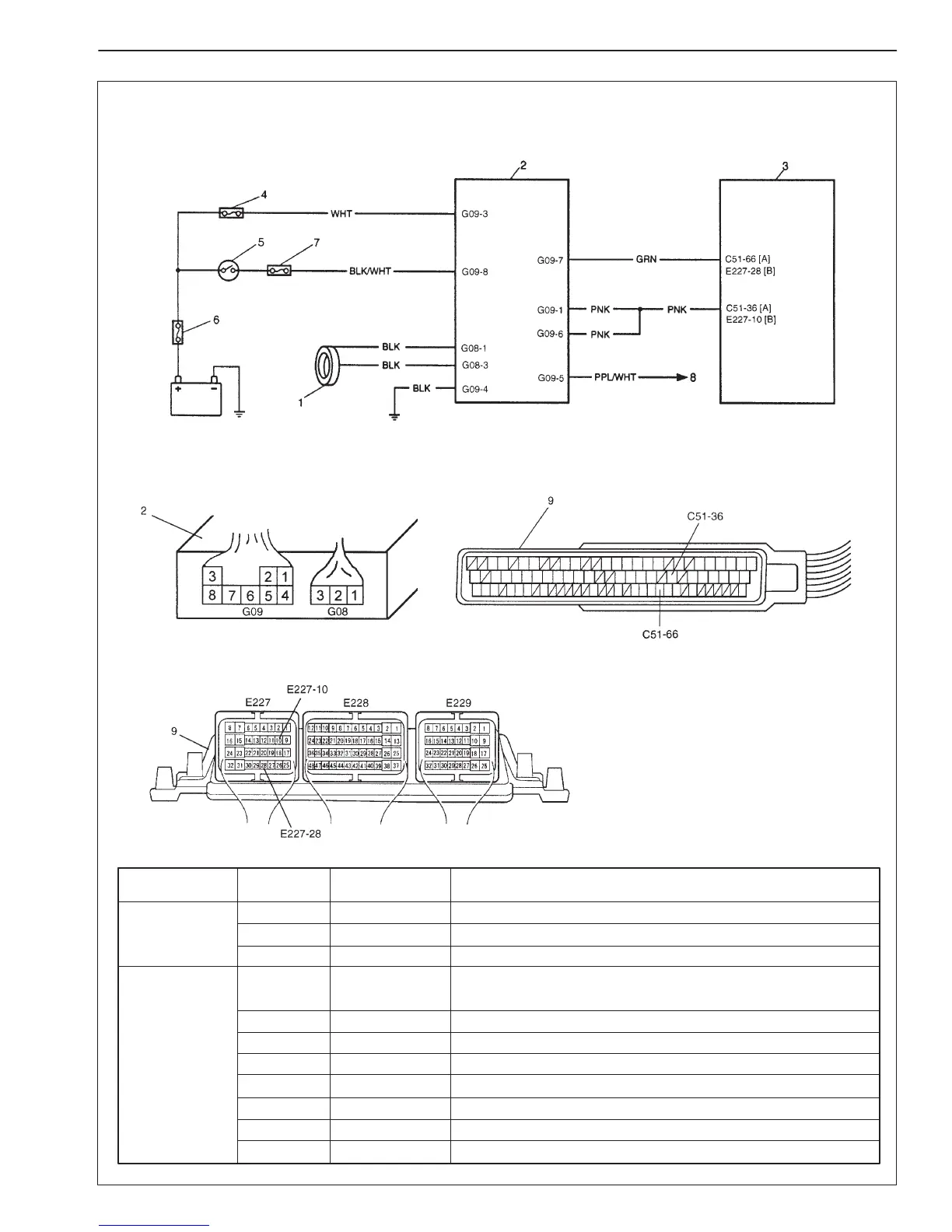
G08 1 BLK Coil antenna +
2– –
3 BLK Coil antenna –
G09 1 PNK Serial data line between ECM and immobilizer control
module
2– –
3 WHT Power supply
4 B GND
5 PPL/WHT Serial data line for Suzuki scan tool
6 PNK Serial data line between ECM and immobilizer control module
7 GRN Power control of ECM
8 BLK/WHT Ignition signal
1. Coil antenna
2. Immobilizer control module
3. ECM
4. “DOME” fuse
5. Ignition switch
6. Main fuse
7. “IG METER” fuse
8. To data link connector
9. ECM connector (Viewed from terminal side)
[A] : For vehicle equipped with single-connector ECM
[B] : For vehicle equipped with triple-connector ECM
CONNECTOR TERMINAL WIRE COLOR CIRCUIT
[A]
[B]

 Loading...


