If the cable is damaged or needed to be replaced, the operation must be
carried out by the after-sale agent with dedicated tools to avoid any accidents.
If the appliance is being connected directly to the mains an Omni-polar
ci
rcuit-breaker must be installed with a minimum opening of 3mm between
co
ntacts.
The installer must ensure that the correct electrical connection has been made
and that it is compliant with safety regulations.
The cable must not be bent or compressed.
The cable must be checked regularly and replaced by authorized technicians
only.
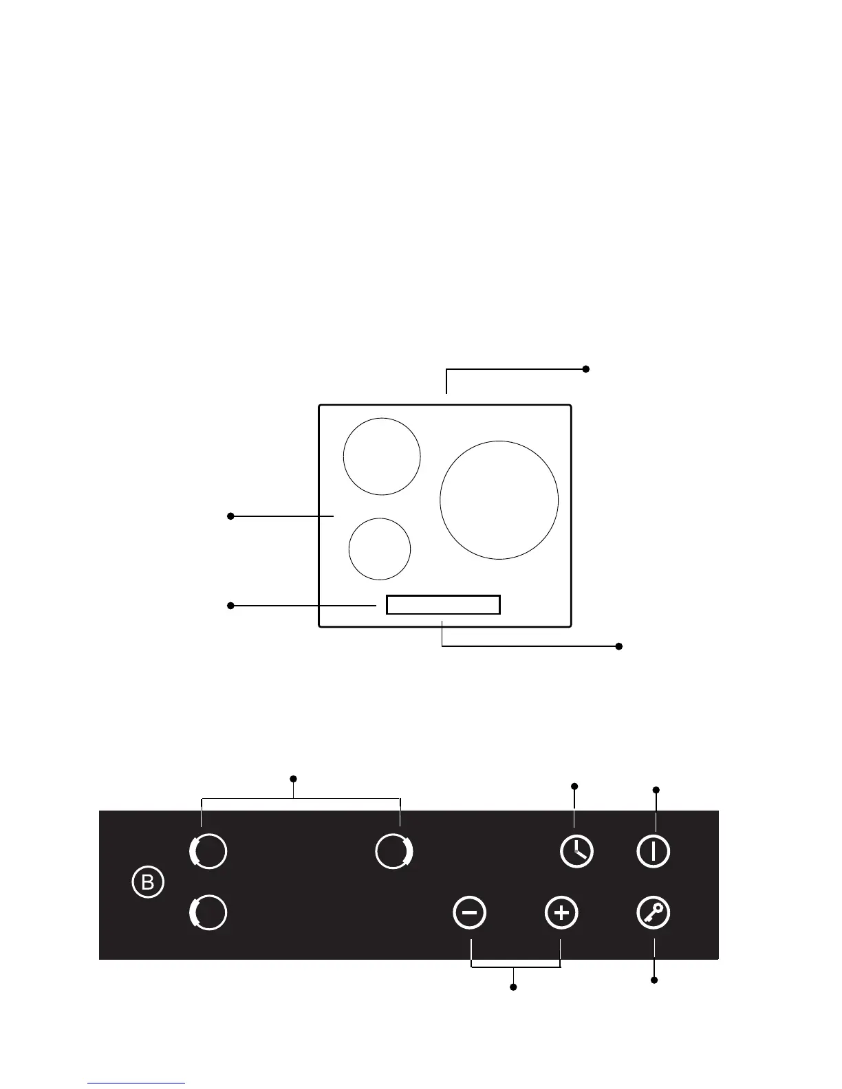
Induction Hotplate Appearance
Figure (6)
Air entry
Air vent
Ceramic plate
Control panel
1
2
3
Schematic Diagram of The Control Pane
l
Boost
23