ENG
6
2.1 Multimedia
Speaker System
Installation and operation
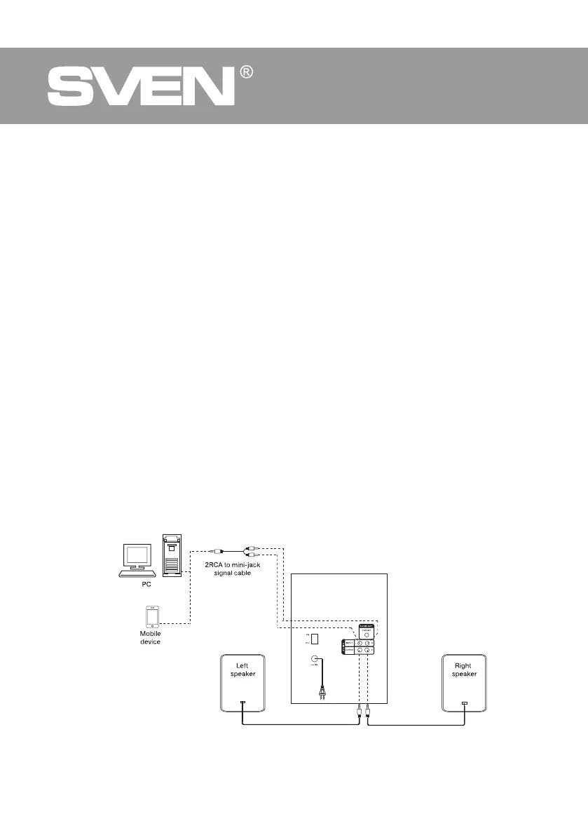
MS-2080 speaker system can be connected to virtually any audio devices: PCs, laptops, etc. (see
connection diagram in Fig. 5).
• Before making any connections, make sure the MSS is off and unplugged. And the ON/OFF
switch is in the OFF position. Then connect speakers to the subwoofer AUDIO OUTPUT m.
Observing the polarity connect the right speaker to the subwoofer AUDIO OUTPUT R with the
audio cable and the left speaker – to the AUDIO OUTPUT L (see connection diagram in Fig. 5).
• To connect the MSS to a PC, mobile device use 2RCA to mini-jack signal cable (included).
Con-
nect the RCA jacks of the signal cable to the L and R jacks of the AUDIO INPUT
l
, and the mini-
jack (
Ø
3.5 mm) of the signal cable – to the LINE OUT port of your PC sound card or to the audio
output mobile device, as shown in Fig. 5.
• Connect the subwoofer to the mains outlet with the power cord
j
.
• Turn on the MSS using button ST-BY
b
on the front panel or button
q
on the remote control.
• Select a desired signal source pressing short button
b
on the control panel or pressing buttons
b, e, s, t
on the remote control.
• Adjust the master volume as desired with buttons VOL-, VOL+
e, f
on the control panel or
pressing buttons VOL+/-
d, m
on the remote control.
• Adjust the bass level using TRE+/-j buttons on the remote control. The timbre level of the
system can be also adjusted using buttons e, fon the control panel preselecting this option
with MENU button c.
• Use SW+/- buttons f on the remote control to adjust the subwoofer volume level. The volume
level of the subwoofer can be also adjusted using buttons e, f on the control panel preselecting
this option with MENU button c.
• In order to have the high-fi gninetsil nehw noitcerid deriuqer a ot annetna eht tcerid noitpecer ytiled
the radio, first connect antenna to RADIO ANT jack k (see Fig. 5).
• When the MSS operation is over, mind to switch it off using ON/OFF switch (i, OFF position) and
unplug the power cord j from the socket.
Fig. 5. Connection diagram
 Loading...