EasyManua.ls Logo

Swegon Actionair ThermShield FD - User Manual

Swegon Actionair ThermShield FD
28 pages
Print Icon
To Next Page IconTo Next Page
Loading...
INSTALLATION GUIDE
ThermShield Standard Installation Method
(Square/Rectangular)
Applies to...
Actionair ThermShield FD
Health and safety
This process must be undertaken by competent per-
sons. More than one person may be required to ensure
the safe handling of large dampers and other materi-
als. Use must be made of access equipment to ensure
unsafe practices are not used to approach walls or dif-
cult access areas.
Standard site PPE should be used (minimum steel toe
cap boots, hard hat); together with any protective
eyewear, gloves and masks, when drilling or cutting is
being undertaken. The latter should also be used when
handing the wall construction materials, as dened by
the material suppliers. If loud equipment is being used,
hearing protection should be used.
All waste materials should be collected and disposed of
as dened by the relevant supplier.
Actuators: All wiring should be carried out in accor-
dance with the wiring details provided by the IEE and
BS regulations and by a competent person. Care must
be taken when installing and inspecting dampers, as
they are likely to close without warning due to loss of
electrical power or a temperature rise in the ductwork.
This is their prime function. Do not insert any items,
ngers or limbs between the blades. Larger dampers
must be handled in accordance with current regula-
tions and good practice due to weight.
Contents
Applies to... .......................................... 1
Health and safety .................................. 1
CE Installation Method Overview ..................... 2
Fire damper installation openings ..................... 3
Rigid wall installation (mortar sealing)............. 4
Rigid wall installation (mineral wool sealing) .. 5
Rigid wall installation (Fire Batt) ....................... 6
Flexible wall installation (mortar sealing) ........ 7
Flexible wall installation (mineral wool
sealing) ................................................................ 8
Flexible wall installation (Fire Batt) ................... 9
Rigid floor/ceiling installation (mortar
sealing) .............................................................. 10
Rigid floor/ceiling installation (Fire Batt) ....... 11
Suspension for mortarless floor installation .. 12
Suspension for mortarless ceiling installation 13
Suspension for mortarless installation close to
ceiling ................................................................. 14
Battery assembly installation 2x2 ................... 15
Battery assembly installation (floor/ceiling)
2x2 ..................................................................... 16
Battery assembly installation 1x2 ................... 17
Minimal seperation damper installation ......... 18
Periodic maintenance ............................ 20
Actuators ............................................21
Wiring Diagrams .................................. 24
Dimensional Data ................................. 26
Inspection and handover check sheet ........ 28
Question and Answer IconNeed help?

Do you have a question about the Swegon Actionair ThermShield FD and is the answer not in the manual?

Summary

Health and Safety

CE Installation Method Overview

Rigid wall installation (mortar sealing)

Method for installing dampers in rigid walls using mortar sealing.

Flexible wall installation (mortar sealing)

Method for installing dampers in flexible walls using mortar sealing.

Rigid floor;ceiling installation (mortar sealing)

Method for installing dampers in rigid floors/ceilings using mortar sealing.

Suspension for mortarless floor installation

Method for suspending dampers in mortarless floor installations.

Fire Damper Installation Openings

Rigid Wall Installation (Mortar Sealing)

Rigid Wall Installation (Mineral Wool Sealing)

Rigid Wall Installation (Fire Batt)

Flexible Wall Installation (Mortar Sealing)

Flexible Wall Installation (Mineral Wool Sealing)

Flexible Wall Installation (Fire Batt)

Rigid Floor;Ceiling Installation (Mortar Sealing)

Rigid Floor;Ceiling Installation (Fire Batt)

Suspension for Mortarless Floor Installation

Suspension for Mortarless Ceiling Installation

Suspension for Mortarless Installation Close to Ceiling

Battery Assembly Installation 2 x2 & 2 X1

Battery Assembly Installation (Floor;Ceiling) 2 x2 & 2 X1

Battery Assembly Installation 1 x2

Minimal Separation Distance Installation

Flexible Wall Subframe

Support for Installation with Mortar

Periodic Maintenance

Manufacturer Recommended Service Intervals

Schedule of maintenance tasks and their recommended frequency.

BS EN 15650:2010 - Ventilation for Buildings - Fire Dampers

Regulatory requirements for fire damper testing and inspection.

Approved Document B, Volume 2

Requirements for access to fire dampers for inspection and maintenance.

Actuators

Manual Actuators R, R-S

Description of manual operating mechanisms for fire dampers.

R25

Details on the R25 manual actuator for FD25 fire dampers.

R40

Details on the R40 manual actuator for FD40 fire dampers.

Technical Specifications

Key technical data for manual actuators, including voltage and switching capacity.

Electric Actuators M24-S & M230-S

Technical Specifications

Technical data for Belimo M24-S and M230-S actuators, including voltage and running time.

Electric Actuator Schischek ExMax

Technical Specifications

Technical data for Schischek ExMax actuators, including torque and running time.

Wiring Diagrams

Manual Actuators R, R-S

Wiring schematics for manual actuators, showing limit switch connections.

Electric Actuator M24-S & M230-S

Wiring diagram for M24-S and M230-S electric actuators with terminal descriptions.

Dimensional Data

Manual

Dimensional data for manual fire dampers (FD25 and FD40).

FD25

Specific dimensions and drawings for the FD25 damper model.

FD40

Specific dimensions and drawings for the FD40 damper model.

Automatic

Actuator

Table of dimensions for different automatic actuator types.

BFL (M)

Dimensional specifications for the BFL (M) automatic actuator.

BFN (M)

Dimensional specifications for the BFN (M) automatic actuator.

BF (M)*

Dimensional specifications for the BF (M)* automatic actuator.

Inspection and Handover Check Sheet

Overview

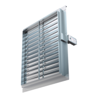
This document outlines the installation, maintenance, and operational characteristics of the ThermShield Standard Square/Rectangular Fire/Smoke Damper, manufactured by Actionair, a Swegon company. The damper is designed for use in fire-separating elements to maintain fire compartments, functioning as an actuated failsafe close damper with low smoke leakage. It is tested to BS EN 1366-2 and classified under BS EN 13501-3, adhering to the Fire Damper Product standard BS EN 15650.

Function Description

The ThermShield fire/smoke damper is a critical component in building fire safety systems. Its primary function is to prevent the spread of fire and smoke through ductwork in ventilation and air conditioning systems. The damper is designed to automatically close upon detection of fire or smoke, effectively sealing off the affected compartment. This "failsafe close" mechanism ensures that in the event of power loss or a temperature rise in the ductwork, the damper will move to its closed position without warning, fulfilling its core safety purpose. The damper blade, when closed, is located inside the fire partition structure.

The damper's operation can be initiated by a thermal fuse melting (typically at 72 °C, with an optional 95 °C setting for inside or outside the duct) or by manual activation on the operating mechanism. For electric actuators, the damper is delivered in a closed position and opens when connected to a power supply. It then stops when it reaches the fully open end position. In the event of a power failure, the damper automatically closes via a return spring. For manual actuators, the blade is locked in the closed position and can only be opened manually after a thermal fuse melting point of 72 °C has been reached.

Usage Features

The ThermShield damper offers versatile installation options for various wall and floor/ceiling constructions:

  • Rigid Wall Installation (Mortar Sealing): Suitable for concrete block or reinforced concrete walls with a minimum thickness of 100 mm. The damper is inserted into an opening, fixed with screws, and the gap is filled with mortar.
  • Rigid Wall Installation (Mineral Wool Sealing): For concrete block or reinforced concrete walls (minimum 100 mm thick). The gap between the casing and wall is filled with mineral wool and covered with gypsum boards.
  • Rigid Wall Installation (Fire Batt): Designed for concrete block or reinforced concrete walls (minimum 100 mm thick). The space is closed with two layers of mineral wool (density ≥ 140 kg/m³, 50 mm thick, coated on one side) and sealed with intumescent fire-resistant sealant. The damper casing and mineral wool must be coated with 2mm thick fire protection coating.
  • Flexible Wall Installation (Mortar Sealing): For 2x2 plasterboard walls (12.5 mm thick) on a steel frame, with mineral wool (≥ 100 kg/m³) filling the interior. The damper is fixed with self-tapping screws, and the gap is filled with mortar and covered with gypsum boards.
  • Flexible Wall Installation (Mineral Wool Sealing): Similar to mortar sealing for flexible walls, but the gap is filled with mineral wool and covered with gypsum boards, fixed with self-tapping screws.
  • Flexible Wall Installation (Fire Batt): For 2x2 plasterboard walls (12.5 mm thick) on a steel frame, with mineral wool (≥ 100 kg/m³) filling the interior. The space is closed with two layers of mineral wool (density ≥ 140 kg/m³, 50 mm thick, coated on one side) and sealed with intumescent fire-resistant sealant. The damper casing and mineral wool must be coated with 2mm thick fire protection coating.
  • Rigid Floor/Ceiling Installation (Mortar Sealing): For concrete block or reinforced concrete floor/ceiling slabs (minimum 100 mm thick). The damper is fixed with screws, and the gap is filled with mortar.
  • Rigid Floor/Ceiling Installation (Fire Batt): For concrete block or reinforced concrete floor/ceiling slabs (minimum 100 mm thick). The space is closed with two layers of mineral wool (density ≥ 140 kg/m³, 50 mm thick, coated on one side) and sealed with intumescent fire-resistant sealant. The damper casing and mineral wool must be coated with 2mm thick fire protection coating.
  • Suspension for Mortarless Floor/Ceiling Installation: For dry mortarless installations in floor/ceiling slabs using mineral wool. Fire dampers are suspended from solid slabs using threaded rods, with ducts suspended separately. The space between the casing and floor/ceiling is closed with Firestop board (Firebatt) and the damper casing is coated.
  • Suspension for Mortarless Installation Close to Ceiling: For dry mortarless installations in solid or flexible walls, suspended from solid ceiling slabs using threaded rods. The space between the casing and wall is closed with mineral wool and sealed with intumescent fire-resistant sealant. Mineral wool and damper casing must be coated with 2mm.
  • Battery Assembly Installation (2x2, 2x1, 1x2): Allows for multiple dampers to be installed in a grid configuration within concrete block or reinforced concrete walls (minimum 100 mm thick). Connecting frames and plates are used to join the dampers, and the gaps are filled with mortar/gypsum and mineral wool.
  • Minimal Separation Distance Installation: Fire dampers can be installed with a minimal distance of 30 mm between the wall/ceiling and 60 mm from other dampers, using mineral wool (140 kg/m³) up to the flanges.

The damper driving mechanism can be placed on either side of the wall, ensuring easy access for inspection. A bendable fixing bracket and red tape marking the wall limit (125mm from the end of the fire damper) assist in positioning.

Maintenance Features

Regular maintenance is crucial to ensure the continued compliance and effective operation of ThermShield dampers. The manufacturer recommends specific service intervals and procedures:

  • After Commissioning and Handover: Follow a regular service and inspection program to ensure correct operation, adhering to BS EN 15650:2010.
  • Digital Reporting: Utilize a dedicated damper control panel with a digital reporting mechanism (e.g., Actionpac LNS system) for frequent monitoring and remote testing.
  • Six-Monthly Checks (Specialist Persons):
    • Check actuator wiring for damage.
    • Check limit switch wiring for damage.
    • Check damper cleanliness, clean and lubricate if necessary.
    • Check condition of blades and seals, rectify if necessary.
    • Check for blade obstructions.
    • Check damper release mechanism (through activation or thermal fuse device).
    • Check damper is in normal operational position after inspection.
  • Monthly Checks (Facility Manager):
    • Complete actuation of the damper from the control panel (if installed) and check all faults. Consult specialist persons for reported faults.
  • BS EN 15650:2010 Requirements: Regular testing/inspection should be undertaken at intervals not exceeding six months. A comprehensive maintenance procedure is detailed in Annex D of the standard.
  • Approved Document B, Volume 2: Adequate means of access must be provided for inspection, testing, and maintenance of both the fire damper and its actuating mechanism.
  • BS 9999:2017 - Smoke Control Systems:
    • Three-Monthly: Simulate actuation of all smoke control systems, testing all zones separately to ensure fans, exhaust ventilators, and smoke dampers operate correctly.
    • Yearly: Annual inspections and tests by competent persons for fire detection and alarm systems, self-contained luminaires, sprinkler/drencher/watermist systems, smoke ventilators, smoke control systems, and fire dampers. Any defects must be logged and rectified.
  • BS 9999:2017 - Air Conditioning and Ventilation Equipment:
    • Maintenance of air conditioning and ventilation equipment, including fire dampers and their controls, is paramount.
    • Fire dampers must be tested by a competent person upon installation and at regular intervals not exceeding two years. Spring-operated fire dampers should be tested annually.
    • Dampers in dust-laden atmospheres require more frequent testing, suited to the degree of pollution.

All wiring should be carried out by a competent person in accordance with IEE and BS regulations. During installation and inspection, care must be taken as dampers can close without warning. No items, fingers, or limbs should be inserted between the blades. Larger dampers must be handled according to current regulations and good practice due to their weight. All waste materials should be collected and disposed of as defined by the relevant supplier.

Swegon Actionair ThermShield FD Specifications

General IconGeneral
TypeFire and Smoke Damper
BrandSwegon Actionair
ModelThermShield FD
LeakageClass 1
Operating Temperature-20°C to +50°C
MaterialGalvanized steel
InsulationOptional insulation available
ApplicationHVAC systems
SizesAvailable in various sizes
MaterialsGalvanized steel
ActuationElectric
ControlManual
StandardsBS EN 1366-2, BS EN 13501-3

Related product manuals