3
20210615 - L00010 Swegon reserves the right to alter specications.
ThermShield Standard Square/Rectangular Installation Guide
Fire damper installation
openings
The FD25 / FD40 re damper is always tested in
standardised support frames (both in a concrete wall and
in a exible wall) in accordance with EN 1366-2: 2015
table 3/4/5. The results obtained are valid for all similar
support frames which have a thickness and / or density
and / or re resistance similar or greater than the one of
the tests.
The duct connected to the re damper must be
supported or hung in such a way that the damper does
not carry its weight. The damper must not support
any part of the surrounding construction or wall which
could cause damage and consequent damper failure.
It is recommended to connect the damper to a exible
connection on either end of the damper.
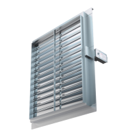
The damper driving mechanism can be placed on either
side of the wall, however it needs to be placed so as to
ensure easy access during inspection.
The gap in the installation opening between the re
damper and the wall/ceiling can be increased by up
to 50% of the gap area, or decreased to the smallest
dimension (B + 60 x H + 60)
• The installation must comply with the tests that were
performed during certication
• Avoid any obstruction of the moving blade by the con-
nected ducts
• The class of air-tightness is maintained in case the
installation of the damper is made in accordance with
the technical manual
• General operating temperature: 50 °C max
• For indoor use only
All dampers can be installed with the blade axis in a
horizontal position or a vertical position in all installation
types except installation remote from the wall and battery
installation. The re damper must be installed into a re
partition structure in such a way that the damper blade
in its closed position is located inside this structure.
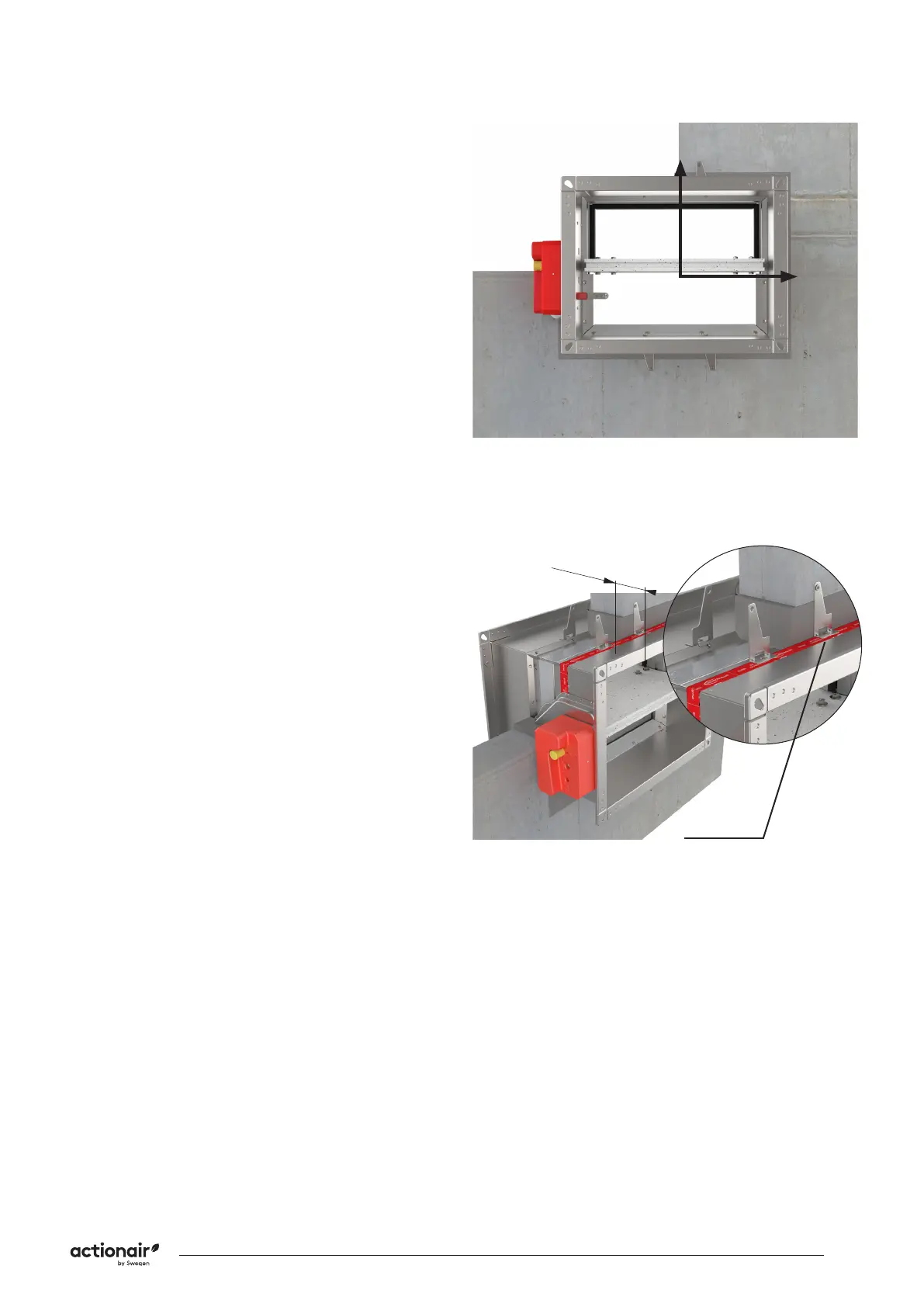
To help you nd the suspension plane, a bendable xing
bracket is provided on the damper body and the red tape
is placed on the casing to mark the location of the wall
limit (distance from wall limit to the end of re damper
is 125mm). This does not apply for Applique / MF2 kit
installations.
Check the operation of the re damper before
commencing the installation!
WALL LIMIT
125 mm
 Loading...