58
We reserve the right to make changes without any prior notice.Translation from original instructions
7.3.2 FlowzerDT
The “DT” function is designed to change the pump speed in order to have a constant temperature dierence between the
unit inlet and outlet.
The resulting eect is that the temperature of water supplied to the system is constant. When the load is reduced, the water
ow rate is reduced accordingly, which results in consumption saving.
The controller keeps the ow rate through the unit within a range of safety values in order to preserve it in good operating
condition.
This function is designed for application on dierent types of hydraulic circuit in the system that are connected to the unit.
Depending on the application, attention must be paid to the construction arrangements of the system.
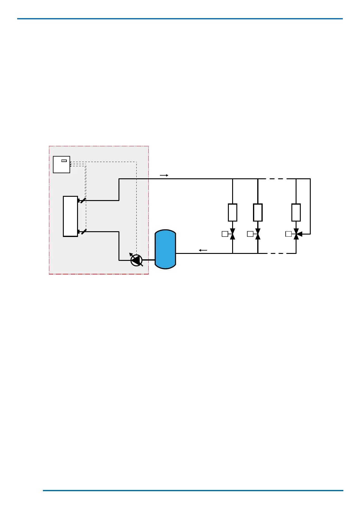
7.3.2.3 System type 1
The pump in the unit is also used for circulating water in the system.
A sample diagram is shown below.
Vmin.
U2
U1
Un
Y2V Y2V
Y3V
VP
A2
UL
UE
BT2
BT1
The abbreviations present in the diagram indicate:
- A2 = cooling unit controller
- BT1 = unit input temperature sensor
- BT2 = unit output temperature sensor
- EU = heat exchanger in cooling unit
- VP = variable ow pump
- U1, U2 .. Un = points of use present in the system/plant
- Y2V = 2-way valve servo controls
- Y3V = 3-way valve servo controls
- Vmin = minimum water volume in the system/plant
- UL = limit of the supply.
This type of system requires that the min. water ow rate is also guaranteed when there is no load. This is made possible
through the installation of 3-way valves on the user points.
The installation of 3-way valves on the furthest user points also provides for greater thermal ywheel, which enables limiting
the capacity of the buer tank.
 Loading...