5
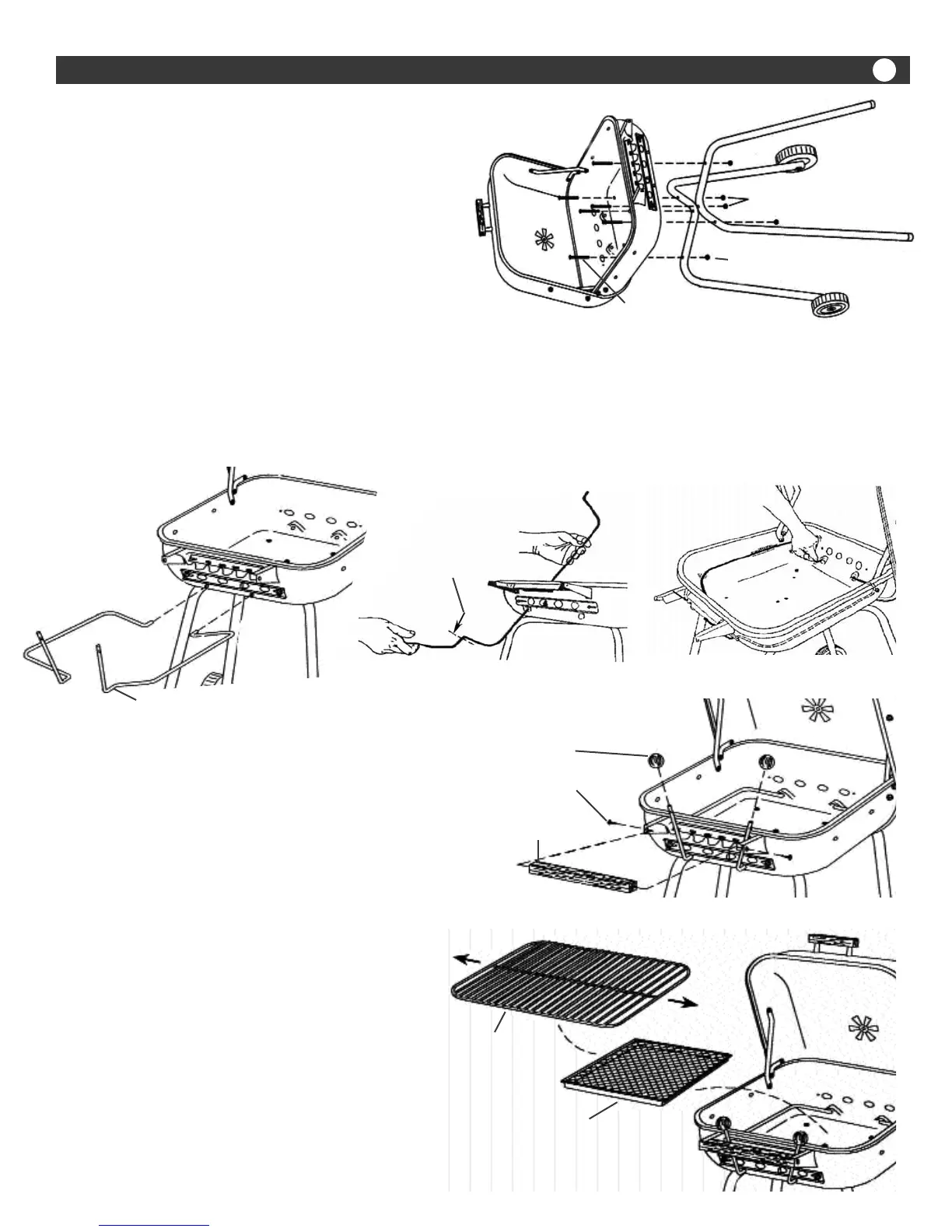
Step 8
Fire Grate / Ash Pan - Cooking Grid Assembly
Install the Fire Grate/Ash Pan in bottom of Bowl.
Place the Cooking Grid on top of Grid Adjusting
Rods. (FIG. 8) Make sure Grid center wires under-
neath are oriented side to side for easy glide height
adjustment. (See Arrows)
Step 5
Bowl / Leg Assembly
Place Hood and Bowl Assembly on a protective pad
or the carton cut out flat on the floor. (FIG. 5) Lay
Hood and Bowl Assembly on its back side with Hood
resting toward the floor.
Align the leg holes with holes in bottom of bowl and
install six 10-24 x 1 1/4” Bolts from inside the bowl
through the legs. Attach six Square Nuts and tighten.
Step 6
Adjusting Rod Assembly
Insert the end of the Left Hand Adjusting Rod into the hole underneath the Slide Vent on the left side of Bowl. (FIG.
6A) Push and twist the Rod through the hole until the end reaches the hole at the rear of the Bowl. (FIG. 6B) Fit the
Rod into one of the notches on the left side of the Control Bracket and pull on the back end of the Rod to let the end
spring into a rear hole. (FIG. 6C)
Make sure the part of the rod inside the Bowl lays to the left when in its lowest position. Repeat for the Right Hand
Adjusting Rod. Check to be sure you can position each Rod into each of the three notches in the Control Bracket.
Step 7
Knob and Bowl Handle Assembly
Position the holes in the Adjusting Rod Knobs over the ends of
the Rods. (FIG. 7) Drive the Knobs on with a rubber or wood-
en mallet. If using a hammer, use the handle end to drive the
knobs on instead of the metal head.
Position the Bowl Handle inside the ends of the Control
Bracket. Insert two #8 x 5/8” Screws through the side holes in
the Bracket and into the Handle. Tighten both screws securely.
FIG. 5
Square Nut
10-24 x 1 1/4” Bolt
FIG. 7
Adjusting Rod
Knobs
Bowl
Handle
#8 x 5/8” Screw
FIG. 6A FIG. 6B FIG. 6C
Left
Adjusting Rod
INSERT UP TO
THIS POINT
Right Adjusting Rod
FIG. 8
Cooking Grate
Fire Grate / Ashpan