DIGIEYE COMPACT Informazioni di base
EN-UM-DGI.CO2.A
Rev. 1.4
Page 7
Use LAN1 / LAN2 ports to connect the Digieye to the network. Up to 2 networks
can be connected to the system, with different management modes
(backup/load-balance/dual-homing). If you use only 1 network, use the LAN1
port. Network interfaces are of the 10/100/1000 Base-T/Base-TX (self-adaptive)
kind. We recommend to use professional network switch and shielded cables
CAT-5e (minimum) to achieve optimal network performances.
4. Analog Cameras Connection (mod. DVR/HVR)
In DVR/HVR units, connect the analog cameras through the multi-BNC adapter
cables provided, to VIDEO IN ports.
The DigiEye COMPACT unit is not provided with loopthrough BNC video output.
5. Inputs/Outputs connection
The DigiEye COMPACT unit is provided with:
4 opto-isolated inputs, dry contacts (potential free) – common GND
2 relay Outputs (24VDC/1A), potential free – with maximum load of 1A at
24 Vdc for each output.
The following chart shows the contacts available on the terminal :
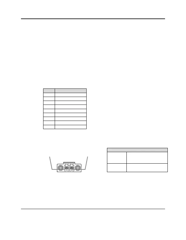
6. Power Supply
Connect the power supply to 4 poles Mini-DIN socket on the rear of the unit.
The connector has the following pinout:
The DigiEye unit is supplied with an AC-DC transformer12Vdc/5A.
DigiEye COMPACT starts as soon as it receives power.
For all eventualities, DigiEye is protected against reverse polarity of the input
voltage.
For EN 50130-4 DigiEye must be connected to a UPS system.
9 – 30 Vdc
(recommended
12Vdc)
 Loading...