7. Using the 425
The 425's design emphasizes ease-of-use. This doesn't mean that we made it easy to use by
removing everything except the power switch; instead we concentrated on keeping the controls
that really make a particular feature work well and eliminating those that didn't. This section
contains installation information and descriptions of each of the front and rear panel controls,
switches, and connectors.
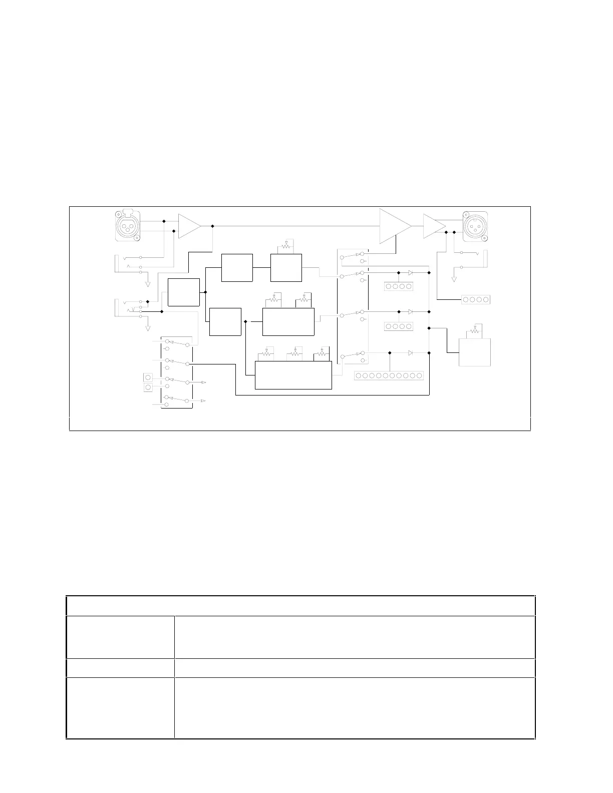
7.1 Block Diagram
Figure 7-1 is the block diagram of the 425.
OUTPUT
UNBALANCED
OUTPUT
BALANCED
UNBALANCED/
BALANCED
INPUT
BALANCED
INPUT
IN/OUT
SIDECHAIN
(EXCEPT OUTPUT LEDS)
TO ALL CH2 LEDS
+V
+V
STEREO LED
DUAL LED
VCA CONTROL VOLTAGE
TO/FROM CH2
SIDECHAIN
TO/FROM CH2
LINK SWITCH
(SHOWN IN STEREO)
OUTPUT LEDS
LEVEL
OUTPUT
GAIN
SWITCH
IN/OUT
EXPANDER LEDS
THRESHOLD
RELEASE
COMPRESSOR LEDS
RATIORELEASETHRESHOLD
LIMITER LEDS
THRESHOLD
CIRCUIT
COMPRESSOR
CIRCUIT
EXPANDER
LIMITER
CIRCUIT
RMS
CIRCUIT
PEAK
CIRCUIT
AMP
LOG
VCA
SSERP
Figure 7-1. Block Diagram (one channel shown).
Please take a moment and take note of the following:
❒ There is only one VCA per channel.
❒ Bypass mode is not a hard-wire bypass for each channel.
❒ The TRS, and XLR input connectors are all paralleled.
❒ The TRS output jack is wired for unbalanced operation (tip hot, ring and sleeve grounded).
7.2 Installation
The 425 may be installed free-standing or rack mounted. No special ventilation requirements
are necessary.
Installation Requirements
Mechanical One rack space (1.75 inches) required, 10 inches depth (including
connector allowance). Rear chassis support recommended for road
applications.
Electrical 105-125 VAC, 50-60Hz, 12.5 Watts maximum.
Connectors XLR-3 female for inputs, XLR-3 male for outputs, Pin 2 of the XLR
connectors is "Hot." TRS female connectors are also provided.
Note: the unbalanced output uses a TRS output jack with the ring
and sleeve connections connected to circuit ground.
7-1
Rev 2.0, 10/29/93