7.3 The 425 as a Compressor
You can use the 425 as a compressor in two different ways:
1. the compressor operates occasionally, dispatching occasional peaks.
2. the compressor operates continuously, making the dynamic range smaller at the output.
For the first scenario, pick a threshold setting that results in occasional gain reduction, as
displayed on the compressor display. Use a ratio setting suitable for your application; low
(1.3:1 to 2.5:1 for gentle compression, higher for more drastic squashing). Low ratios are
harder to hear, consequently you can operate with 6 dB or so of compression, without too
many audible effects. Higher ratios require subtlety, especially in threshold selection. Pick
your threshold setting so that no more than 6 dB of gain reduction occurs and you'll get the
signal control that you need, without being too obvious. Pick a release setting that lets the
gain recover fairly quickly.
Scenario two requires low ratio settings (unless you don't care about being obvious), and a
lower (-10 or lower) threshold setting. Choose a threshold setting that results in more or less
continuous gain reduction. Pick the ratio setting so that the dynamic range of the output
signal corresponds to the maximum and minimum signal levels that you want. Pick a release
setting that allows gain recovery during longer pauses.
7.4 The 425 as a Ducker
Well, almost. First, what is a ducker? (Hint: It's not something twisted utilizing waterfowl.) It is
a way of making the level of one audio signal follow that of another. A prime example would be
an announcer (the ducker) talking over a music bed (the duckee). What most people do is to
simply ride the music facer when the announcer is talking. You can do the same thing
automatically by using a compressor having a sidechain connection.
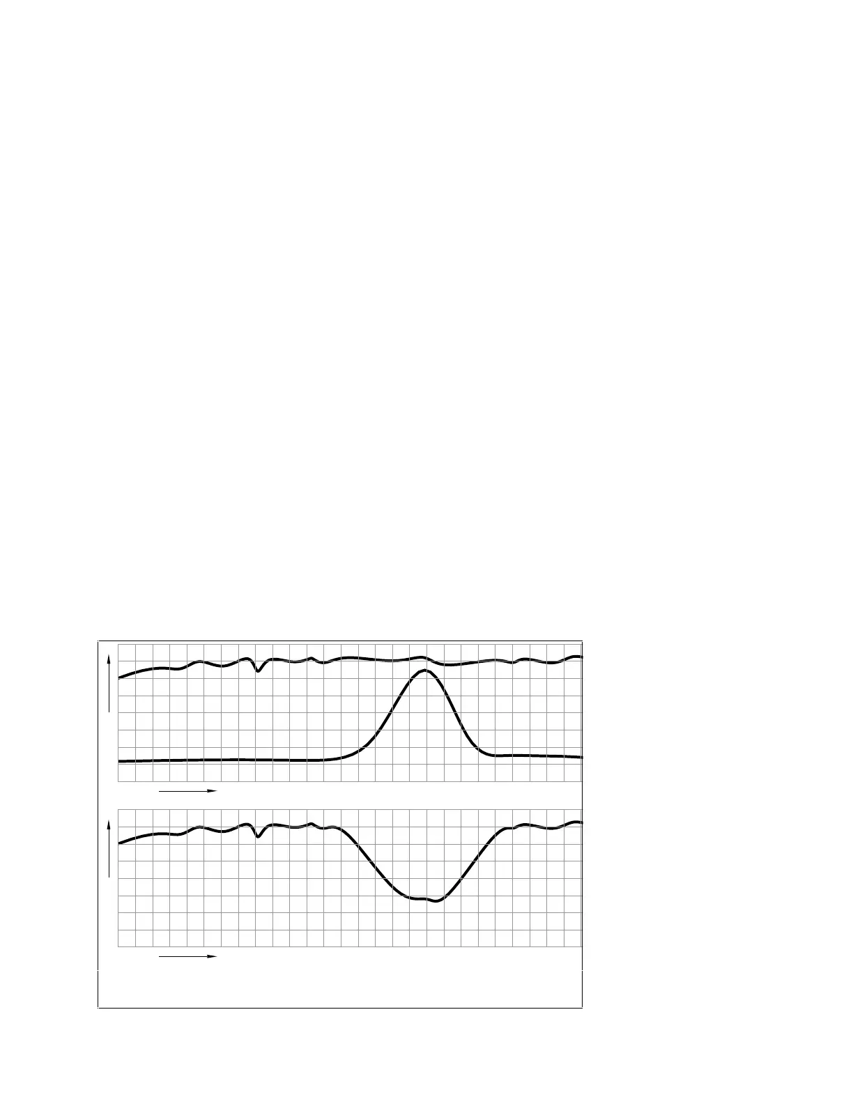
Now for some people, a "true" ducker must reduce the level of the duckee to some preset level
whenever the ducker signal is present. The 425 will not do this. It will,however, reduce the
level of the duckee whenever the ducker is present, but the amount of gain reduction follows
the envelope of the
ducker signal. Get it?
See Figure 7-1 for a
more graphic
description.
TIME
V
LUME
TIME
V
LUME
OUTPUT
DUCKER
DUCKEE
Figure 7-1. Signal relationships in a ducker.
Anyway, if this
"limitation" isn't a
problem, then refer to
Section 8.4 for
hookup. The ratio
control determines the
talkover ratio (how
much the duckee gets
reduced for a change
in the ducker) and the
threshold control
determines the total
amount of ducking
action. The release
time control govern's
how rapidly the
Rev 2.0, 10/29/93
7-2