628
5
Gain adjustment ...
The remaining task in setting up your 628 input signal is adjustment of the input GAIN attenuator.
This sets up proper gain structure through the 628s A/D converter. First set the push buttons of
the De-esser, Expander/Gate, Compressor and Parametric EQ to the bypass position. All of the
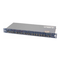
ACTIVE LEDs will be off. Turn the OUTPUT LEVEL until 0 (unity gain) shows on the MASTER
display below the LED headroom display on the right side of the 628.
While speaking into the microphone in your best announcer voice, or while feeding the 628 line
level audio, adjust the input GAIN attenuator until the LED headroom display peaks at an average
of -8 dBfs. All of the green LEDs and the first yellow LED will light. Its OK if the second yellow
LED (-4 dBfs) flashes on occasional loud peaks.
Take care not to clip the input preamplifier. Check this by using your loudest normal voice when
setting the input GAIN attenuator. We found that a knob position of 12 o'clock is about right for
dynamic microphones. Too much gain applied in the preamplifier also adds unnecessary noise in
the signal path.
Note: The 628s GAIN control adjusts either the microphone preamplifier gain or the
line input level depending on which input is selected.
Where’s the VU meter?
Whats this headroom meter stuff? The analog 528 and 528E use an LED VU meter. There is no
"0" on the 628's meter. When 528s and 528Es hit 0 dB on the analog meter, the output is 0 dBm
(+4 dBu). The output of these analog processors is referenced to 600 milliwatts into a 600 ohm
load.
Digital audio equipment references signal levels to the clip point. With digital equipment, there is
no 0 dBm reference point. A signal passing through the 628 at a level of -4 dBfs (dB full scale) is
4 dB below clipping, NOT at -4dBu. The 628 clips at +22 dBu. This means that the -4 dBfs signal
equates to +18 dBu (4 dB below +22 dBu).
The THRESHOLD controls and metering in the Compressor, Downward Expander and De-esser
sections of the 628 are also referenced to the clip point (0 dBfs). When a threshold is set for -10.0
dB, it is set at 10 dBu below clipping, or at a value of +12 dBu.
Lets compare the difference between a VU meter and a headroom meter with the speedometer in
your car. Your speedometer is like a VU meter. When you travel at 55 m.p.h. (the legal speed limit,
in this example), the speedometer reads 55. 55 m.p.h. is an absolute speed just as 0 dBm is an
absolute voltage. If you travel at 45 m.p.h., your analog speedometer would read 45 m.p.h..
A headroom speedometer would express the speed limit (55 m.p.h.) as 0 m.p.h.. If you travel at
45 m.p.h., the headroom speedometer would display -10 m.p.h.. The headroom speedometer
tells you that you are traveling at a speed 10 m.p.h. below the legal limit. You could speed up
another 10 m.p.h. before getting clipped by the cops.
You always want to drive close to the speed limit on the freeway, and the input of digital audio
equipment should be operated as close to the clip point of the A/D converter as possible. This
assures the best resolution of the digital signal. A signal passing through the 628 which registers
-4 dBfs on the headroom meter produces 20-bit audio. A signal passing through with peaks of only
-20 dBfs renders only 14-bit audio. Best digital resolution and optimum signal-to-noise perfor-
mance dictates that you keep audio passing through the 628 as high as possible on the headroom
meter.
Lets move around back again and connect the 628 output.