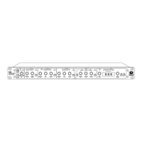
628
6
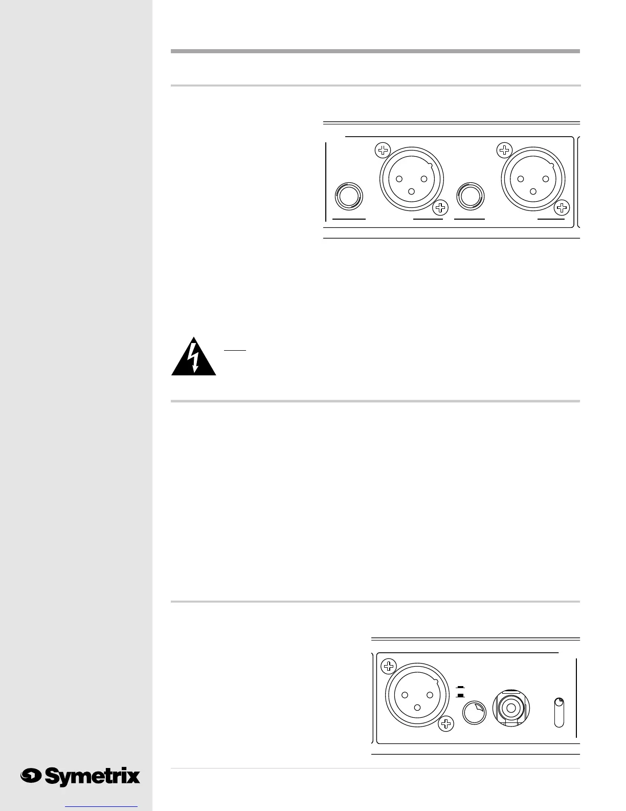
If you plan to use the balanced, line level (+4 dBu) output, the job is easy. Plug a properly wired 3
pin, female XLR connector into one of the analog output connectors. Pin #2 is high (+), pin #3 is
low (-) and pin #1 is circuit ground.
You will notice that we provided
two outputs, ANALOG LEFT and
ANALOG RIGHT. You may use
either, or both.
When you need an analog
unbalanced line level output,
please use one, or both, of the 1/4
inch TS (Tip/Sleeve) jacks. The tip
is high (+); sleeve is ground (-).
The analog output of the 628 may seem higher than the output of your 528 or 528E. Youre right!
Because we want to operate digital circuits closer to the clip point, the analog output signal will
also operate closer to its clip point. If this presents a problem by overloading your console input,
turn down the input trimmer for that channel. If your console does not provide an input trimmer,
insert a fixed pad between the analog output of the 628 and your console input. You may also load
the output of the 628 with a 620 ohm resistor when connecting it to a balanced, bridging input.
Connect the resistor across the high (+) and low (-) connections at the console input.
Note: You may be tempted to simply turn down the OUTPUT LEVEL control on the
628. This is a digital gain control. Remember that digital devices perform
better when operated close to their clip point.
But, I need a mic level output ...
We recommend that you use a line level analog output whenever possible. But, in the real world,
things arent always this neat. Some consoles only allow microphone level (-50 dBu) inputs for the
channels providing microphone functions (such as speaker muting or on-air light switching).
Please call your console manufacturer and complain loudly about their lack of flexibility. Any
quality console input should provide switching between microphone and line level.
Dont expect much help from the console guys. Thats OK; we built a solution into the 628. When
backed against the wall, you may convert one, or both, XLR analog outputs of the 628 to micro-
phone level output.
Warning: This change is accomplished inside the box via jumpers and must be made by a
qualified electronic technician. A technician can find instructions for this procedure
in Appendix C of this manual. You may return your 628 to us for conversion if you do
not have a qualified technician available. Please call our Customer Service Depart-
ment for a return authorization number.
SAMPLE
OUTPU
U
SELECT
48kHz
S/P DIF
AES/EBU
44.1kHz
32kHz
S/P DIF
RATE
AES/EBU
SELECT
DIGITAL OUTPUT
And, I want the digital output ...
Making use of the 628s digital output requires a few more steps. First determine the sample rate
which you need to feed to your digital input. Move the SAMPLE RATE SELECT toggle switch to
the proper sample rate setting. You must use
sample rates of 48 kHz, 44.1 kHz or 32 kHz.
The 628 makes no provision for synchroniza-
tion to an external clock.
The DIGITAL OUTPUT SELECT switch
activates one of the two digital outputs. The
AES/EBU output appears on the 3 pin, male
XLR connector. The Sony/Phillips Digital
Interface (S/P DIF) output is on the RCA pin
Under normal circumstances ...
PUTS
UNBALANCED
ANALOG RIGHT
UNBALANCED
ANALOG LEFT