Symmons Industries, Inc. ■ 31 Brooks Drive ■ Braintree, MA 02184 ■ Phone: (800) 796-6667 ■ Fax: (800) 961-9621
Copyright © 2019 Symmons Industries, Inc. ■ symmons.com ■ gethelp@symmons.com ■ ZV-3291 REV 0 ■ 031919
WARNING: This product can expose you to chemicals including lead, which is known to the state of California to cause cancer, birth defects, or
other reproductive harm. For more information, go to www.P65Warnings.ca.gov.
Problem Cause Solution
Diverter valve will not divert water.
Foreign matter in water supply may
cause blockages in plumbing lines and
the diverter valve cartridge.
Remove cartridge from diverter valve.
Flush lines free of foreign matter.
Inspect cartridge for debris. Replace
cartridge if necessary.
Water is leaking from the face of the
diverter valve.
Cap assembly is not fully sealed to
diverter valve.
Remove cap assembly. Inspect
threads for debris. Reinstall cap
assembly to diverter valve at
75
±
5
lbf-in of torque.
Diverter trim will not install to diverter
valve.
Diverter valve body rough-in is too
deep.
Use RTS-DIV-1EXT to extend diverter
stem 1 inch.
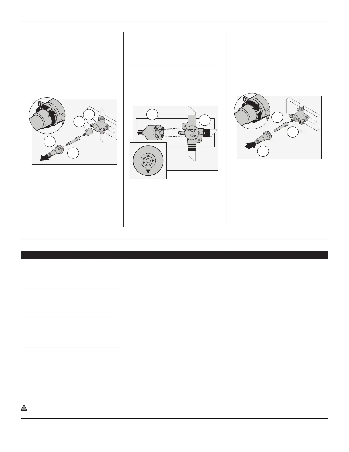
Maintenance (Cartridge Replacement)
2
A
C
D
E
1) Remove cap assembly (A) from
diverter valve by turning coun-
terclockwise. Remove cartridge
extender (C) and cartridge (D). For
diverter valves purchased before
November 2016, remove retaining
sleeve (F) from diverter valve.
3) Orient new cartridge (D) with
arrow facing down. Align pegs on
cartridge (D) with indents inside
diverter valve (E).
D
E
2)
Inspect cartridge for debris.
Replace cartridge if necessary.
4) Align spindle extender (C) with
broach on cartridge (D). Install
spindle extender (C) and cap
assembly (A) to cartridge (D).
Secure cap assembly (A) by
turning clockwise.
D
1
C
A
Notes:
1) Use caution not to dislodge
cartridge from valve body when
installing cap assembly (A).
2) Tighten cap assembly (A) to
75
±
5 lbf-in of torque.
Troubleshooting Chart
Note: Spacer (B) will be seated
inside cap assembly (A).
Note: For diverter valves purchased
before November 2016, retaining
sleeve (F) must be inserted ush into
diverter valve (E) before installing
cartridge (D).