6408 216th Street SW | Mountlake Terrace, WA 98043 USA
T +1.425.778.7728 F +1.425.778.7727 | www.SymetrixAudio.com
8
Quick Start Guide
Multi-RingSystems•DeviceAddresing•RelayOut
Multi-Ring Systems
When using multiple Express devices or integrating Express
and traditional SymNet Rings, there are basically two ways
in which to set up multi-ring systems. The decision to make
is whether you would like to manage the rings as a whole
system from the same Site File or manage the rings as
completely independent systems (unique Site Files).
Interfacing to manage each ring as a separate system can
be done via RS-232 or Ethernet. If by Ethernet, care must
be taken to avoid IP conflicts and accessibility should be
considered - general network design and administration
issues. If by RS-232, separate PCs can be permanently
connected to each ring individually, or one PC could be
meant to ‘roam’ amongst them.
To manage the rings in one Site File as a whole system,
each hardware device must have its own dedicated Ethernet
connection to a common hub, switch, router or existing
network. Any properly set up PC on the network can then
control the system.
Device Addressing
Every Express hardware device contained within a common
Site File must be uniquely identified as its own ring. A Ring
address of 1 through 31 is available. If the Express device
is stand-alone (the only device in the Site File) it must be
Ring 1. The device addresses of the physical hardware
in your system must match the devices as configured in
your SymNet Designer Site File. You may use the pictorial
diagrams below to quickly set up and understand the device
address DIP switches on the Express.
Note: Any time the DIP switches are changed, the device(s)
must be power cycled for the changes to take effect.
Relay Out
The Express provides one (1) SPDT relay contact. Common,
Normally Closed and Normally Open pins are furnished on a
3-pin Euroblock connector. Contact ratings for the relay are:
3 Amp, 24 VDC, resistive; 0.3 Amp, 60 VDC, resistive. Do
not use at 120 VAC. (Please see the SymNet Designer online
help for information on how to address the Relay Output in a
SymNet DSP design.)
Note: This relay can also be used for power failure
detection. This option is set in the I/O Options of the device
Properties dialog. See SymNet Designer online help for more
information.
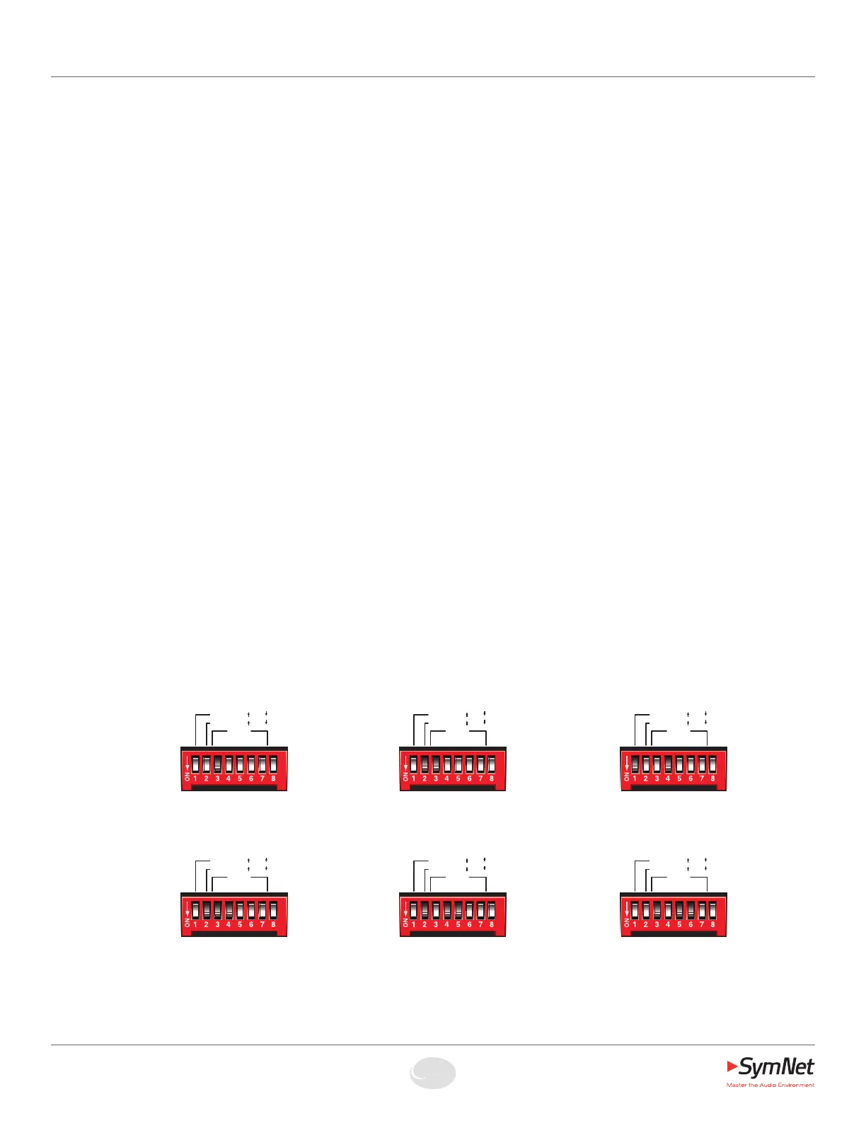
Express DIP Switch Settings
NOTE: For the sake of space, a small variety of congurations are shown.
A total of 31 devices (Rings) per Site File are possible.
RING 13
RS-232 = Host @ 115k
No accessory RS-232
RING 6
RS-232 = Accessory @ 38.4k (default)
Host communications by Ethernet only
RING 3
RS-232 = Accessory @ 38.4k (default)
Host communications by Ethernet only
RING 2
RS-232 = Host @ 57.6k
No accessory RS-232
RING 1
RS-232 = Accessory @ 38.4k (default)
Host communications by Ethernet only
RING 1
RS-232 = Host @ 115k
No accessory RS-232
HOST:
RS-232:
115k 57k/
BOOT MODE
RING
1 2 4 8 16
Host Acc/
HOST:
RS-232:
115k 57k/
BOOT MODE
RING
1 2 4 8 16
Host Acc/
HOST:
RS-232:
115k 57k/
BOOT MODE
RING
1 2 4 8 16
Host Acc/
HOST:
RS-232:
115k 57k/
BOOT MODE
RING
1 2 4 8 16
Host Acc/
HOST:
RS-232:
115k 57k/
BOOT MODE
RING
1 2 4 8 16
Host Acc/
HOST:
RS-232:
115k 57k/
BOOT MODE
RING
1 2 4 8 16
Host Acc/
 Loading...