p a g e
7
In d u s t r I a l pC - COpIlOt 15"
Or d e r CO d e 190331x x x xMa y 2009 - re v . 1.5
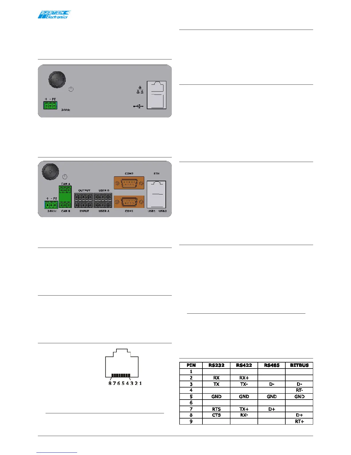
4.2 Connection diagram
of traditional external
connectors
Traditional rear connectors
Figure 4.2.1
Traditional rear connectors full-
version
Figure 4.2.2
24V Power Supply
• 1 +24V
• 2 GND
• 3 PE
24V External Batteries
• 20 +24V
• 21 GND
• 22 NC
Ethernet RJ45
• 1 TX+
• 2 TX-
• 3 RX+
• 4
• 5
• 6 RX-
• 7
• 8
NOTE:
The LEDs of the Ethernet connector are not
used.
USB
• 1 +5V_USB
• 2 D-
• 3 D+
• 4 GND_USB
CAN
• 4 CAN_H
• 5 CAN_L
• 6 CAN_GND
• 7 CAN_H
• 8 CAN_L
• 9 CAN_GND
24V PNP DIGITAL INPUTS
• 15 IN_1
• 16 IN_2
• 17 IN_3
• 18 IN_4
• 19 IN_GND
The terminal recognises an active input when a positive
supply is connected between the IN and GND.
24V PNP DIGITAL OUTPUTS
• 10 OUT_1
• 11 OUT_2
• 12 OUT_3
• 13 OUT_4
• 14 OUT_GND
The outputs are powered by the 24V main input supply
and are not isolated.
NOTE
The UserA and UserB connectors are congured
differently according to the options installed on
request.
COM1 and COM2
Table 4.2.1