p a g e
8
In d u s t r I a l pC - COpIlOt 15"
Or d e r CO d e 190331x x x xMa y 2009 - re v . 1.5
Special connection for the Bitbus
board option with traditional
connectors no DB9
USER B connector for Bitbus connection
• 20 D- (USER_B.1)
• 21 D+ (USER_B.2)
• 22 RT- (USER_B.3)
• 23 RT+ (USER_B.4)
• 24 RGND (USER_B.5)
4.3 Connection diagram of M12
external connectors
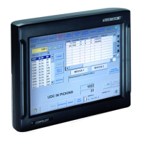
Rear connectors
PWR + 2xUSB + PULS
Figure 4.3.1
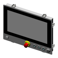
Rear connectors for 4 holes
PWR + ETH + USB
Figure 4.3.2
M12 external connectors (8 holes)
24V+2ETH+USB+2CAN+1RS232
Figure 4.3.3
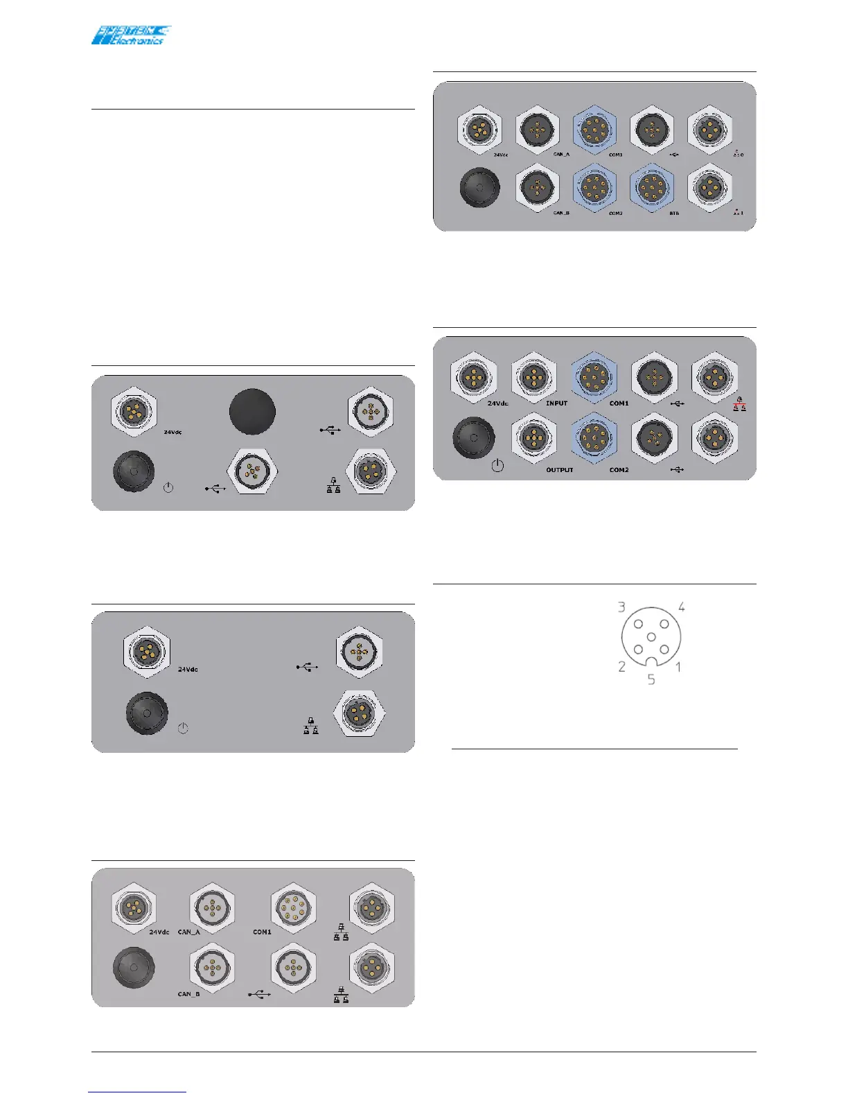
M12 external connectors (10 holes)
Figure 4.3.4
M12 external connectors with I/O
(10 holes)
Figure 4.3.5
24V Power Supply
[M12 Female 5-pole A]
• 1 +24V
• 2 +24V
• 3 GND
• 4 GND
• 5 PE
Figure 4.3.6 View of the external female connector
NOTE
The connection of pins 2 and 4 is set up to
minimise the losses due to cables with a reduced
section. The following alternative connection can
be used if necessary:
• 1 +24V
• 2 n.c.
• 3 GND
• 4 n.c.
• 5 PE