p a g e
9
In d u s t r I a l pC - COpIlOt 15"
Or d e r CO d e 190331x x x xMa y 2009 - re v . 1.5
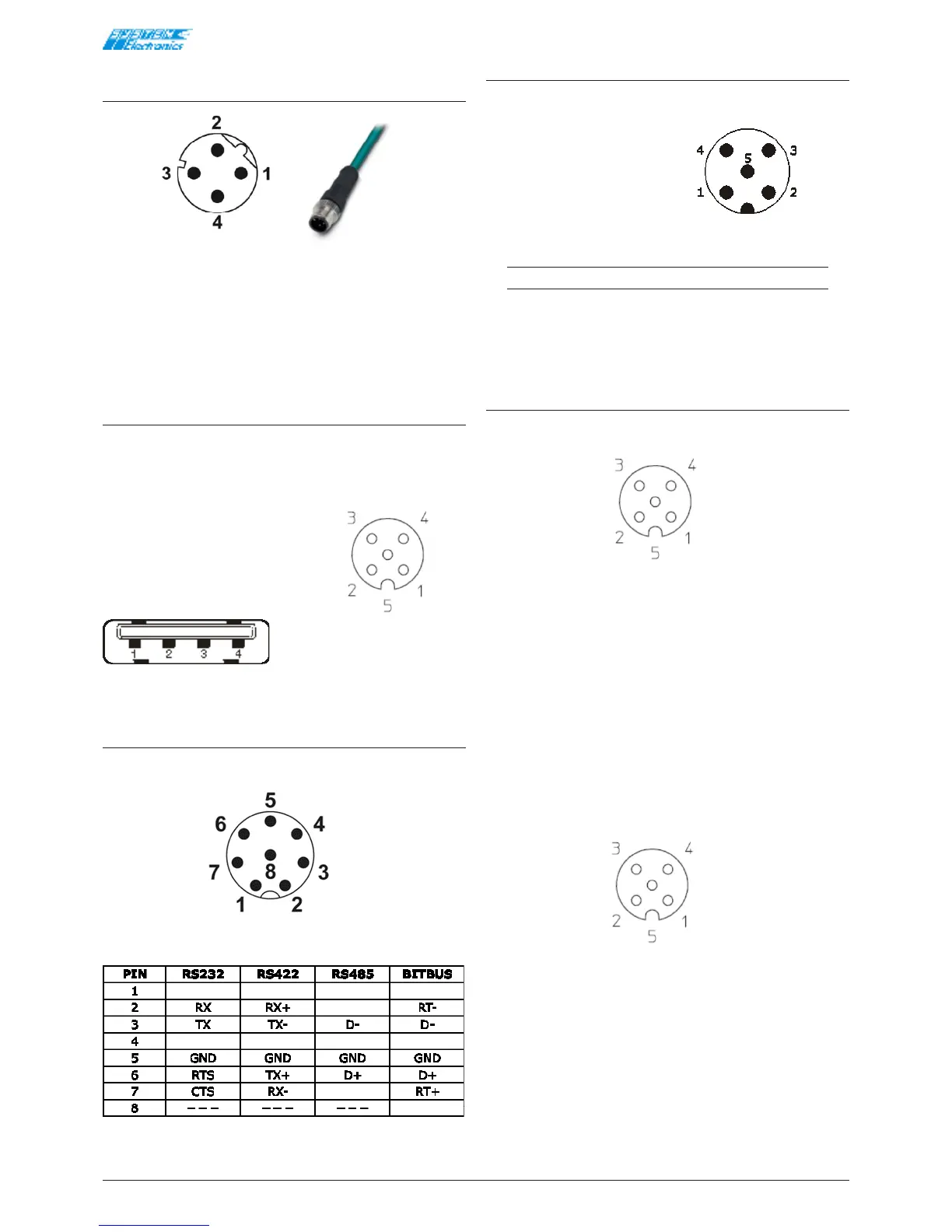
Ethernet (standard IEC 61076-2-
101) [M12 Female polarised D]
Figure 4.3.7 M12 Cable with male connector
• 1 TX+
• 2 RX+
• 3 TX-
• 4 RX-
USB [M12 Male 5-pole A]
Wiring with cable USB 2.0 M12 FEMALE.
Ready-for-use adapters can be provided to connect
devices with a Type-A USB connector.
• 1 5V_USB
• 2 GND_USB
• 3 D+
• 4 D-
• 5 PE
Figure 4.3.9
COM1/COM2 [M12 Male 8-pole]
COM1 Wiring (selected internally as RS232/RS422/
RS485)
Figure 4.3.10 View of the external male connector
Table 4.3.1
CAN Wiring [M12 Male 5-pole A]
Copilot side male (compatible CAN repeater)
• 1 SHIELD
• 2 .
• 3 CAN_GND
• 4 CAN_H
• 5 CAN_L
Figure 4.3.11
Note:
The shield is not connected internally. It is not
recommended to wire the CAN_GND signal but
only CAN_H and CAN_L.
M12 Input and Output Connection
24V PNP Digital Inputs [M12 Female 5-pole A]
Figure 4.3.12 View of the rear connector
• 1 IN_1
• 2 IN_2
• 3 IN_3
• 4 IN_4
• 5 IN_GND
The terminal recognises an active input when a positive
supply is connected between the IN and GND.
24V PNP Digital Outputs [M12 Female 5-pole A]
Figure 4.3.13 View of the rear connector
• 1 OUT_1
• 2 OUT_2
• 3 OUT_3
• 4 OUT_4
• 5 OUT_GND
The outputs are powered by the 24V main input supply
and are not isolated.