D200-66-00 3 I56-997-02
CAUTION
Dust covers are an effective way to limit the entry of dust
into smoke detector sensing chambers. However, they may
not completely prevent airborne dust particles from enter-
ing the detector. Therefore, System Sensor recommends the
removal of detectors before beginning construction or other
dust producing activity. Be sure to remove dust covers from
any sensors that were left in place during construction as
part of returning the system to service.
Testing
NOTE: Before testing, notify the proper authorities that
the smoke detector system is undergoing mainte-
nance and will be temporarily out of service. Dis-
able the zone or system undergoing maintenance
to prevent unwanted alarms.
Detectors must be tested after installation and following
periodic maintenance. Test the 2112TL as follows:
A. Test Switch
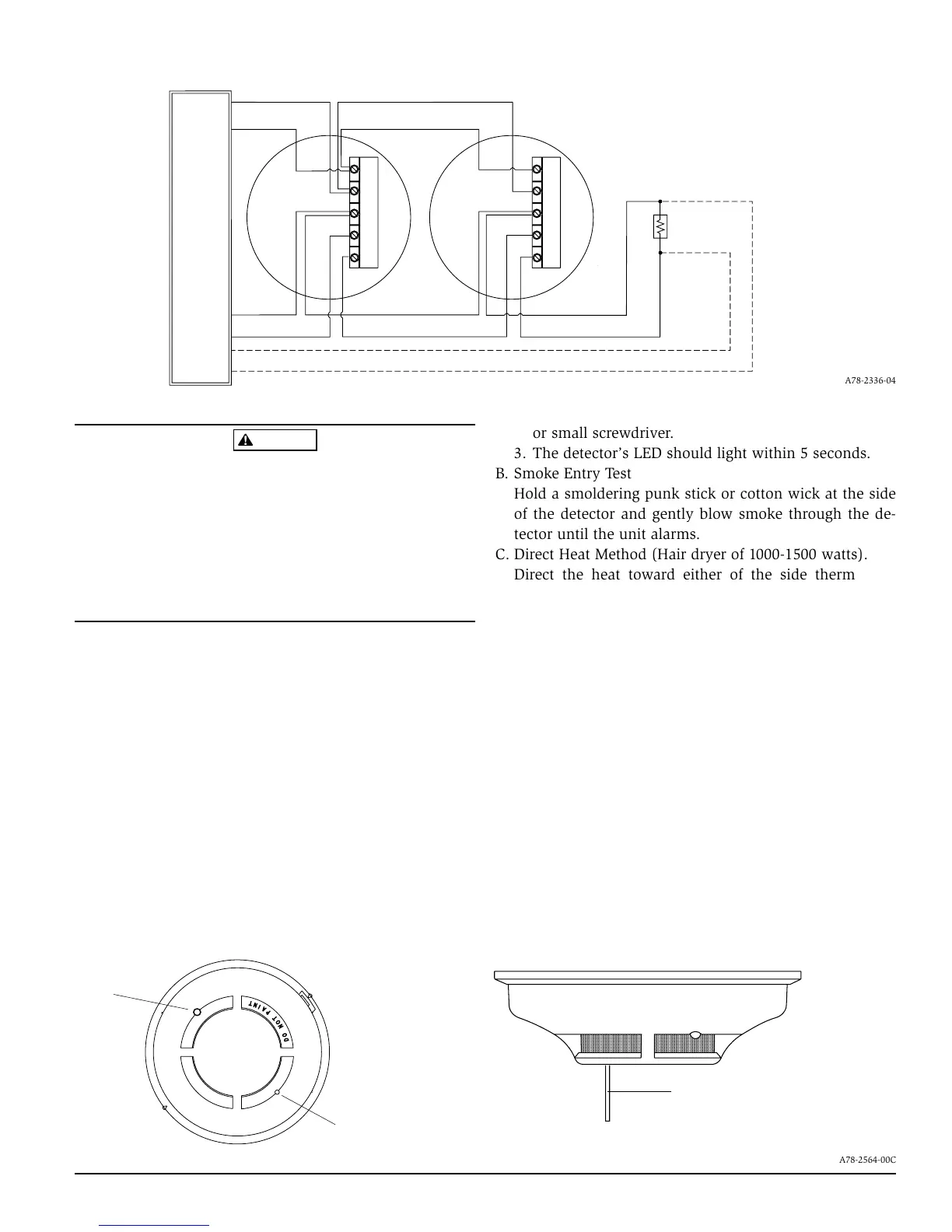
1. A recessed test switch is located on the detector hous-
ing (See Figure 4).
2. Press and hold the recessed test switch with a 0.18
inch maximum diameter tool such as an allen wrench
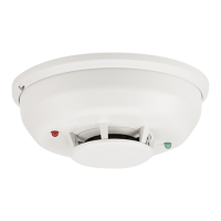
Figure 3. Wiring diagram for the 2112TL detector:
OPTIONAL CLASS A WIRING
EOL RESISTOR
SPECIFIED BY
PANEL
MANUFACTURER
POWER
TO
DETECTORS
UL LISTED
CONTROL
PANEL
INITIATING
LOOP
+
–
+
–
+
Z+
Z-
Z-
–
–
OUT
IN
+
Z+
Z-
Z-
OUT
IN
(See Note 1)
Power
Supervision
}
Note1: This terminal is not electrically connected to the detector's circuit.
It is used for wiring consistency only. Power to the detector is applied across
the "+" and "Z-
IN" terminals.
LED
RECESSED TEST
SWITCH
Figure 4. Top and side views showing position of test switch:
PUSH RECESSED
SWITCH WITH A
0.18″ MAX. DIAMETER TOOL
,,,,,,,,,,,,,,,,,,,,,,,,,
,,,,,,,,,,,,,,,,,,,,,,,,,
,,,,,,,,,,,,,,,,,,,,,,,,,
,,,,,,,,,,,,,,,,,,,,,,,,,
,,,,,,,,,,,,,,,,,,,,,,,,,
,,,,,,,,,,,,,,,,,,,,,,,,,
,,,,,,,,,,,,,,,,,,,,,,,,,
,,,,,,,,,,,,,,,,,,,,,,,,,
,,,,,,,,,,,,,,,,,,,,,,,,,
,,,,,,,,,,,,,,,,,,,,,,,,,
,,,,,,,,,,,,,,,,,,,,,,,,,
,,,,,,,,,,,,,,,,,,,,,,,,,
,,,,,,,,,,,,,,,,,,,,,,,,,
,,,,,,,,,,,,,,,,,,,,,,,,,
A78-2564-00C
A78-2336-04
or small screwdriver.
3. The detector’s LED should light within 5 seconds.
B. Smoke Entry Test
Hold a smoldering punk stick or cotton wick at the side
of the detector and gently blow smoke through the de-
tector until the unit alarms.
C. Direct Heat Method (Hair dryer of 1000-1500 watts).
Direct the heat toward either of the side thermistors.
Hold the heat source about 12 inches from the detector
in order to avoid damage to the plastic. The detector will
reset only after it has had sufficient time to cool and the
power source has been momentarily interrupted.
Both smoke and heat detection testing are recommended
for verifying system protection capability.
A detector that fails to activate with any of the above tests
should first be cleaned as outlined in MAINTENANCE. If
the detector still fails to activate, return it for repair.
Notify the proper authorities the system is in operation.
Maintenance
It is recommended that the detector be removed from its
mounting base to facilitate cleaning.
A78-2564-02A