EasyManua.ls Logo

System Sensor 2151A - User Manual

System Sensor 2151A
4 pages
Print Icon
To Next Page IconTo Next Page
Loading...
D100-04-00 1 I56-1015-000
2151A Low Profile
Photoelectronic Plug-in
Smoke Detector
INSTALLATION AND MAINTENANCE INSTRUCTIONS
6581 Kitimat Rd., Unit #6, Mississauga, Ontario, L5N 3T5
1-800-SENSOR2, FAX: 905-812-0771
www.systemsensor.ca
Before Installing
Please thoroughly read the System Sensor manual I56-
407, Guide for Proper Use of System Smoke Detectors,
which provides detailed information on detector spacing,
placement, zoning, wiring, and special applications. Cop-
ies of this manual are available at no charge from System
Sensor. Please also refer to CAN/ULC-S524-M91, Stan-
dard for the Installation of Fire Alarm Systems, and CEC
Part 1, Sec. 32.
NOTICE: This manual should be left with the owner/user
of this equipment.
IMPORTANT: The detector used with this base must be
tested and maintained regularly following CAN/ULC-S536
requirements. The detector used with this base should be
cleaned at least once a year.
General Description
The 2151A low-prole photoelectronic detector uses a
state-of-the-art optical sensing chamber. This detector
is designed to provide open area protection and to be
used with compatible ULC-listed control panels only. The
capability of plugging the detector into a variety of special
bases makes it more versatile than equivalent direct-wired
models.
Specifications
Size
Height: 1.7 inches (43 mm)
Diameter: 4.0 inches (101 mm)
Weight: 3.6 oz. (102 g)
Operating Voltage: 10 to 32 VDC
Max. Avg. Standby Current: 120uA
Operating Temperature Range: 0° to 49°C (32° to 120°F)
Operating Humidity Range: 10% to 93% Relative Humidity noncondensing
Latching Alarm: Reset by momentary power interruption.
Two LEDs on each detector provide local 360° visible
alarm indication. They ash every ten seconds indicating
that
power is applied and the detector is working properly.
The LEDs latch on in alarm. Remote LED annunciator
capability is standard and may be implemented through
an optional accessory RA400ZA. The alarm can be reset
only by a momentary power interruption. These detectors
may be tested by activating the internal reed switch with a
magnet.
Base Selection And Wiring Guide
Refer to the installation instructions for the Plug-in De-
tector Bases for base selection and wiring instructions.
System Sensor has a variety of detector bases available
for this smoke detector, including 2-wire applications with
and without relays and/or current limiting resistors, 4-wire
and 120VAC applications ( see list below ).
All bases are provided with screw terminals for power,
ground, remote annunciator connections and relay con-
tact connections, if applicable. The electrical ratings for
each detector-base combination are also included in the
base installation instructions.
Adapter Base Selection Guide
Base Model Loop Current Alarm Nominal Current Draw
Number Type Limit Resistor Contact Type Voltage on Alarm (mA)
B110LP 2-wire* No 12/24VDC 10–100**
B112LPA 4-wire Yes Form A&C 24VDC 14–39
B114LPA 4-wire Yes Form A&C + A Supy. 120VAC 75 mA AC Max
B116LPA 2-wire* No Form C 24VDC 12–100**
B401 2-wire* No 12/24VDC 10–100**
*Functionality
contingent on panel compatibility **Must be limited by control panel †Flangeless base
Relay Contact Ratings: Resistive or Inductive (60% power factor) load.
Form A: 2.0A at 30 VAC/DC
Form C: 0.6A at 110VDC, 2.0A at 30VDC - 1.0A at 125VAC, 2.0A at 30VAC
Question and Answer IconNeed help?

Do you have a question about the System Sensor 2151A and is the answer not in the manual?

Summary

General Description

Adapter Base Selection Guide

Installation

Installing Detectors

Describes the process of placing and securing the detector into its base.

Tamper Resistance

Explains how to make detector bases tamper-resistant using a tool.

Post-Installation Steps

Details steps after installing detectors, including power application and system notification.

Testing

Test Magnet Procedure

Outlines the steps for testing the detector using a magnet.

Detector Testing Methods

Test Module (MOD400 R)

Utilizes a DMM or voltmeter to check detector sensitivity.

Aerosol Generator (Gemini 501)

Uses aerosol to simulate smoke for testing detector alarm.

Maintenance

Detector Cleaning Procedure

Step-by-step guide for removing and cleaning the detector's components.

Three-Year Limited Warranty

Overview

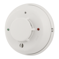
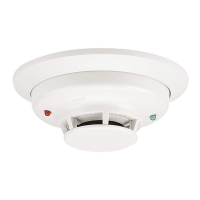
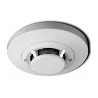
The 2151A Low Profile Photoelectronic Plug-in Smoke Detector is a sophisticated device designed for open area protection in fire alarm systems. It utilizes a state-of-the-art optical sensing chamber to detect smoke and is intended for use with compatible ULC-listed control panels. Its plug-in design allows for greater versatility compared to direct-wired models, as it can be integrated with a variety of specialized bases.

Function Description:

The 2151A detector operates by sensing smoke particles within its optical chamber. When smoke is detected, it triggers an alarm. Two LEDs on each detector provide 360° visible alarm indication. These LEDs normally flash every ten seconds to confirm that power is applied and the detector is functioning correctly. In an alarm state, the LEDs latch on. The detector also supports remote LED annunciator capability, which can be implemented using an optional RA400ZA accessory. An alarm can only be reset by a momentary interruption of power to the device. For testing purposes, the detector features an internal reed switch that can be activated with a magnet.

Important Technical Specifications:

  • Size:
    • Height: 1.7 inches (43 mm)
    • Diameter: 4.0 inches (101 mm)
  • Weight: 3.6 oz. (102 g)
  • Operating Voltage: 10 to 32 VDC
  • Max. Avg. Standby Current: 120uA
  • Operating Temperature Range: 0° to 49°C (32° to 120°F)
  • Operating Humidity Range: 10% to 93% Relative Humidity noncondensing
  • Latching Alarm: Reset by momentary power interruption.

The detector can be used with various adapter bases, each offering different functionalities and electrical ratings. These bases include options for 2-wire applications (with or without relays and/or current limiting resistors), 4-wire applications, and 120VAC applications. All bases are equipped with screw terminals for power, ground, remote annunciator connections, and, where applicable, relay contact connections.

Adapter Base Selection Guide (Examples):

  • B110LP (2-wire*): No current limit resistor, 12/24VDC, 10-100mA current draw on alarm.
  • B112LPA (4-wire): Yes current limit resistor, Form A&C contact type, 24VDC, 14-39mA current draw on alarm.
  • B114LPA (4-wire): Yes current limit resistor, Form A&C + A Supy. contact type, 120VAC, 75mA AC Max current draw on alarm.
  • B116LPA (2-wire*): No current limit resistor, Form C contact type, 24VDC, 12-100mA current draw on alarm.
  • B401 (2-wire*): No current limit resistor, Form C contact type, 12/24VDC, 10-100mA current draw on alarm.
    • *Functionality contingent on panel compatibility.
    • **Must be limited by control panel.
    • †Flangeless base.
  • Relay Contact Ratings (Resistive or Inductive (60% power factor) load):
    • Form A: 2.0A at 30 VAC/DC
    • Form C: 0.6A at 110VDC, 2.0A at 30VDC; 1.0A at 125VAC, 2.0A at 30VAC

Usage Features:

  • Installation: Detectors are installed by placing them into the detector base and turning clockwise until they lock into place.
  • Tamper Resistance: Detector bases can be configured for tamper resistance, preventing removal without a specialized tool.
  • Testing:
    • Test Magnet (System Sensor model no. M02-04-01): Placing a magnet against the designated mark on the detector cover activates the test feature, causing the LEDs to latch ON within 5 seconds and annunciating the panel.
    • Test Module (MOD400R): Used with a DMM or voltmeter to check detector sensitivity.
    • Aerosol Generator (Gemini 501): Applies aerosol to simulate smoke, setting the generator to represent 4% to 5%/ft. obscuration until the unit alarms.
  • Dust Covers: While effective in limiting dust entry, dust covers do not guarantee complete prevention of airborne particles. System Sensor recommends removing detectors before construction or other dust-producing activities and removing any remaining dust covers before returning the system to service.

Maintenance Features:

  • Regular Testing and Maintenance: The detector, when used with its base, must be tested and maintained regularly according to CAN/ULC-S536 requirements.
  • Annual Cleaning: The detector, when used with its base, should be cleaned at least once a year.
  • Cleaning Procedure:
    1. Notify authorities and disable the system to prevent unwanted alarms.
    2. Remove the detector cover by prying away the four side tabs with a small-bladed screwdriver.
    3. Carefully vacuum the screen. If further cleaning is needed, proceed to the next step.
    4. Remove the screen assembly by pulling it straight out and vacuum the inside.
    5. Clean the vaned chamber piece by vacuuming or blowing out dust and particles.
    6. Replace the screen, ensuring the arrow on top aligns with the arrow on the printed circuit board, and push it tightly onto the vaned chamber.
    7. Replace the cover by gently pushing it until it locks in place.
    8. Reinstall the detector and notify authorities that the system is back online.
  • Troubleshooting: If LEDs do not blink, the detector may have lost power or be defective and should be returned for repair. Detectors that fail testing after cleaning should also be returned for repair.

Warranty:

System Sensor provides a Three-Year Limited Warranty, ensuring the smoke detector is free from defects in materials and workmanship under normal use and service for three years from the date of manufacture. The company's obligation is limited to the repair or replacement of defective parts. To claim warranty service, contact System Sensor for a Return Authorization number and send defective units postage prepaid. The warranty does not cover damage due to unreasonable use, modifications, or alterations. The company is not liable for consequential or incidental damages.

System Sensor 2151A Specifications

General IconGeneral
BrandSystem Sensor
Model2151A
CategorySmoke Alarm
LanguageEnglish

Related product manuals