D400-02-01 REV#-002 1 I56-1020-000
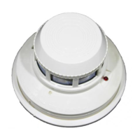
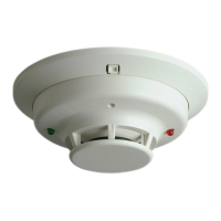
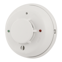
2451A Photoelectronic Plug-in
INSTALLATION AND MAINTENANCE INSTRUCTIONS
Before Installing
Please thoroughly read the System Sensor publication,
I56-407, Applications Guide for System Smoke Detectors,
which provides detailed information on detector spacing,
placement, zoning, wiring, and special applications. Cop-
ies of this guide are available at no charge from System
Sensor. Please also refer to CAN/ULC-S524, Standard
for the Installation of Fire Alarm Systems and CEC Part 1,
Sec. 32..
NOTICE: This manual should be left with the owner/user
of this equipment.
IMPORTANT: This sensor must be tested and maintained
regularly following CAN/ULC-S536 requirements. This
sensor should be cleaned at least once a year.
General Description
The 2451A photoelectronic detector utilize state-of-the-art,
optical sensing chambers. This detector is designed to pro-
vide open area protection, and to be used with compatible
ULC-listed control panels only. The capability of plugging
this detector into a variety of special bases makes it more
versatile than equivalent direct-wired models.
Two LEDs on each detector light to provide a local 360°
visible alarm indication. They ash every ten seconds indi-
cating that power is applied and the detector is operating
properly. The LEDs light continuously in alarm. Remote
LED annunciator capability is available as an optional ac-
Specifications
Size
Height: 2.4 inches (61 mm)
Add 0.5 inches (13 cm) for thermal model 2451THA
Diameter: 4.0 inches (101 cm)
Weight: 0.5 lb. (277 g)
Operating Temperature Range: 0° to 49°C (32° to 120°F)
Operating Humidity Range: 10% to 93% Relative Humidity
Maximum Air Velocity: 3000 Ft./Min. (15 M/S)
Locking Alarm: Reset by momentary power interruption
Fixed Temperature Thermal: 135°F (57°C)
cessory. This detector also has the Latching Alarm feature.
The alarm can be reset only by a momentary power inter-
ruption. This detector may be tested by activating the inter-
nal reed switch with a magnet, or by inserting a calibrated
test card in a test slot after removing the detector cover.
Base Selection and Wiring Guide
Refer to the installation instructions for the Plug-in Detector
Bases for base selection and wiring instructions. System
Sensor has a variety of detector bases available for this
smoke detector. This includes 2-wire applications with and
without relays and/or current limiting resistors, 4-wire and
120VAC applications.
All bases are provided with screw terminals for power,
ground, remote annunciator connections and relay contact
connections, if applicable. The electrical ratings for each
detector-base combination are also included in the base
installation instructions.
Installation
NOTE: Wiring must conform to applicable local codes,
ordinances, and regulations.
NOTE: Verify that all detector bases are installed, that the
initiating-device circuits have been tested, and
that the wiring is correct. (Refer to detector base
manual for testing procedure.)
Smoke Detectors
6581 Kitimat Rd., Unit #6, Mississauga, Ontario, L5N 3T5
1-800-SENSOR2, FAX: 905-812-0771
www.systemsensor.ca