EasyManua.ls Logo

System Sensor 2412TH - User Manual

System Sensor 2412TH
24 pages
Print Icon
To Next Page IconTo Next Page
Loading...
D400-07-00 1 I56-279-03
1400 Direct Wire Ionization
Smoke Detector
INSTALLATION AND MAINTENANCE INSTRUCTIONS
A Division of Pittway
3825 Ohio Avenue, St. Charles, Illinois 60174
1-800-SENSOR2, FAX: 630-377-6495
Before Installing
Please thoroughly read the System Sensor manual I56-407-
XX, Guide for Proper Use of System Smoke Detectors. This
manual provides detailed information on detector spacing,
placement, zoning, wiring, and special applications. Copies
of this manual are available at no charge from System Sen-
sor. (For installation in Canada, refer to CAN/ULC-S524,
Standard for the Installation of Fire Alarm Systems and CEC
Part 1, Sec. 32.)
General Description
System Sensor 1400 dual-chamber ionization smoke detec-
tors utilize state-of-the-art, unipolar sensing chambers.
These detectors are designed to provide open area protec-
tion, and to be used with compatible UL-listed, 2-wire con-
trol panels only. The detector’s operation and sensitivity
can be tested in place.
Specifications
Diameter: 5.5 inches (140 mm)
Height: 3.12 inches (80 mm)
Weight: 0.7 lb. (310 g)
Operating Temperature: 0
o
to +49
o
C (32
o
F to 120
o
F)
Latching Alarm: Reset by momentary power interruption.
Operating Humidity: 10% to 93% Relative Humidity, Noncondensing
Electrical Ratings:
System Voltage: 12/24 VDC
Maximum Ripple Voltage: 4 Volts peak to peak
Start-up Capacitance: 0.02 uA Maximum
Standby Ratings: 8.5 VDC Minimum
35 VDC Maximum
100 uA Maximum
Alarm Ratings: 4.2 VDC Minimum at 10 mA
6.6 VDC Minimum at 100 mA
Alarm current must be limited to 100 mA maximum by the control panel. If used, the
RA400Z Remote Annunciator operates within the specified detector alarm currents.
Reset Voltage: 2.5 VDC Minimum
Reset Time: 0.3 S Maximum
Start-up Time: 35 S Maximum
Each detector includes an LED that provides a local visual
indication of the detector’s status. The LED blinks every ten
seconds as an indication that power is applied to the detec-
tor and lights continuously in alarm. These detectors also
have the latching alarm feature. The alarm can be reset
only by a momentary power interruption.
The detector also has provision for the connection of an
optional Model RA400Z Remote Annunciator. The RA400Z
provides a visual indication of an alarm and mounts to a
single gang box.
Spacing
NFPA 72 defines the spacing requirements for smoke detec-
tors. Typically, this is 30 feet when the detectors are in-
stalled on a smooth ceiling. However, ALL installations
must comply with NFPA 72 and/or special requirements of
the authority having jurisdiction.
Technical Manuals Online! - http://www.tech-man.com
Question and Answer IconNeed help?

Do you have a question about the System Sensor 2412TH and is the answer not in the manual?

Summary

1400 Series Ionization Smoke Detector

1400 Series Specifications

Key physical and environmental parameters for the 1400 series smoke detector.

1400 Series Electrical Ratings

Details on voltage, current, and power requirements for the 1400 series detector.

1400 Series Wiring Installation Guidelines

Best practices and requirements for wiring the 1400 series smoke detector system.

1400 Series Installation Steps

Step-by-step guide for installing the 1400 series smoke detector.

1400 Series Testing Procedures

Procedures for verifying the 1400 series smoke detector's functionality after installation.

1400 Series Maintenance Guide

Routine cleaning and care instructions for the 1400 series smoke detector.

1412 and 1424 Series Ionization Smoke Detectors

1412;1424 Series Specifications

Key physical, environmental, and electrical parameters for the 1412/1424 series models.

1412;1424 Series Electrical Ratings

Details on voltage, current, and power requirements for the 1412/1424 series models.

1412;1424 Series Installation Steps

Step-by-step instructions for installing the 1412/1424 series detectors.

1412;1424 Series Testing Procedures

Methods for testing the functionality of the 1412/1424 series smoke detectors.

2400 and 2400 TH Series Photoelectronic Smoke Detectors

2400;2400 TH Series Specifications

Technical details including size, operating conditions, and electrical ratings for 2400/2400TH series.

2400;2400 TH Series Installation Steps

Step-by-step guide for installing the 2400/2400TH series smoke detectors.

2400;2400 TH Series Testing Procedures

Methods for testing the 2400/2400TH series smoke detectors' functionality.

2400 AT and 2400 AIT Series Photoelectronic Detectors

2400 AT;2400 AIT Series Specifications

Technical specifications for the 2400AT/2400AIT series, including thermal features.

2400 AT;2400 AIT Series Testing Procedures

Methods for testing the 2400AT/2400AIT series smoke detectors.

2412 AT, 2424 AT, and 2424 AIT Series Photoelectronic Detectors

2412 AT;2424 AT;2424 AIT Specifications

Technical details for 2412AT, 2424AT, and 2424AIT series models.

2412 AT;2424 AT;2424 AIT Electrical Ratings

Electrical specifications including voltage, current, and relay ratings for these models.

2412 AT;2424 AT;2424 AIT Testing Procedures

Methods for testing the 2412AT, 2424AT, 2424AIT series detectors.

2412, 2412 TH, 2424, and 2424 TH Series Photoelectronic Detectors

2412;2412 TH;2424;2424 TH Specifications

Key parameters for 2412/2412TH and 2424/2424TH series models.

2412;2412 TH;2424;2424 TH Electrical Ratings

Electrical specifications including voltage, current, and relay ratings for these series.

2412;2412 TH;2424;2424 TH Installation Steps

Step-by-step guide for installing the 2412/2424 series detectors.

2412;2412 TH;2424;2424 TH Testing Procedures

Methods for testing the 2412/2424 series smoke detectors.

Overview

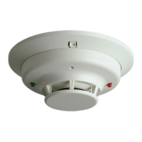
This document describes several models of direct wire smoke detectors from System Sensor, including ionization and photoelectronic types, with and without fixed heat detection and audible signals.

Function Description:

The System Sensor 1400 series consists of dual-chamber ionization smoke detectors that utilize state-of-the-art, unipolar sensing chambers. These detectors are designed for open area protection and are compatible with UL-listed, 2-wire control panels. They feature a latching alarm that can only be reset by a momentary power interruption. An integrated LED provides local visual status indication, blinking every ten seconds in standby and lighting continuously in alarm. These detectors also offer a provision for connecting an optional Model RA400Z Remote Annunciator, which provides a supplementary visual alarm indication and mounts to a single gang box.

The System Sensor 1412 and 1424 models are dual-chamber ionization smoke detectors designed for open area protection and use with UL-listed, 4-wire control panels. The 1412 operates at 12VDC, and the 1424 operates at 24VDC. Like the 1400 series, they are latching type system detectors, requiring a momentary power interruption to reset. An LED blinks every 10 seconds in standby and latches on continuously in alarm. Each detector includes one Form A (SPST-NO) contact for the alarm-initiating circuit and one Form C (SPDT-NO/NC) set of auxiliary contacts. Power supervision is achieved by installing a Power Supervisory End-of-Line Relay Module (A77-716) at the end of the detector power loop. A power failure or break in the loop de-energizes the EOL Module, triggering a trouble signal at the control panel.

The System Sensor 2400 and 2400TH are photoelectronic smoke detectors that use state-of-the-art, optical sensing chambers. They are designed for open area protection and are compatible with UL-listed 2-wire control panels. The 2400TH model additionally features a restorable, built-in, fixed temperature (135°F) thermal detection unit. These detectors are UL 268 listed and are latching type, requiring a momentary power interruption for reset. An LED blinks every 10 seconds in standby and latches on continuously in alarm. They also provide an output for connecting an optional Model RA400Z Remote Annunciator.

The System Sensor 2412AT, 2424AT, and 2424AIT are photoelectronic smoke detectors with fixed heat detection, listed to UL 268, and designed for open area protection with UL-listed, compatible, 2-wire control panels. The 2412AT operates at 12 VDC, while the 2424AT and 2424AIT operate at 24 VDC. These sensors utilize a light scattering principle with a unique photo-optic sensing chamber. They include restorable 135°F fixed-temperature heat detection. The 2400AT and 2412AT/2424AT heat detection units are integrated with the photoelectronic sensor, while the 2424AIT's heat detection unit is isolated and can be monitored separately. Additionally, a piezoelectric horn in each detector produces an interrupted, 85 dBA tone when the individual detector alarms or when the supply voltage polarity is reversed. An LED provides a local alarm indication, remaining on when the supply polarity is reversed. A screw terminal is provided for a remote LED annunciator (RA400Z). These are latching type detectors, reset by momentary power interruption. Each detector contains one Form A (SPST-NO) contact for the alarm-initiating circuit and one set of Form C auxiliary contacts. Power supervision is achieved by installing a Power Supervisory End-of-Line Relay Module (A77-716) at the end of the detector power loop.

Important Technical Specifications:

Direct Wire Ionization Smoke Detector:

  • Diameter: 5.5 inches (140 mm)
  • Height: 3.12 inches (80 mm)
  • Weight: 0.7 lb. (310 g)
  • Operating Temperature: 0° to +49°C (32°F to 120°F)
  • Operating Humidity: 10% to 93% Relative Humidity, Noncondensing
  • System Voltage: 12/24 VDC
  • Standby Ratings: 8.5 VDC Minimum; 35 VDC Maximum; 100 uA Maximum
  • Alarm Ratings: 4.2 VDC Minimum at 10 mA; 6.6 VDC Minimum at 100 mA (current limited to 100 mA max by control panel)
  • Reset Voltage: 2.5 VDC Minimum
  • Reset Time: 0.3 S Maximum
  • Start-up Time: 35 S Maximum

and 1424 Direct Wire Ionization Smoke Detectors:

  • Diameter: 5.5 inches (14 cm)
  • Height: 3.12 inches (8.0 cm)
  • Weight: 0.7 lb (310 gm)
  • Operating Temperature: 0° to +49°C (32° to 120°F)
  • Operating Humidity: 10% to 93% Relative Humidity Non-condensing
  • Relay Contact Ratings (Resistive or Inductive 60% power factor load):
    • Form A: 2.0A @ 30VAC/DC
    • Form C: 0.6A @ 110VDC, 2.0A @ 30VDC; 1.0A @ 125VAC, 2.0A @ 30VAC (Canadian installations: 2.0A @ 30VAC/DC)
  • System Voltage: 12 (1412) / 24 (1424) DC (4V Maximum Ripple)
  • Supply Voltages: 11.3 VDC Min (1412) / 20 VDC Min (1424); 17.3 VDC Max (1412) / 29 VDC Max (1424)
  • Standby Current: 100 µA Maximum
  • Alarm Currents: 35.2 mA Min (1412) / 21.3 mA Min (1424); 77.0 mA Max (1412) / 40.6 mA Max (1424)
  • Reset Time: 0.3 Seconds
  • Start-up Time: 30 Seconds

and 2400TH Direct Wire Photoelectronic Smoke Detectors:

  • Diameter: 5.5 inches (140 mm)
  • Height: 3.14 inches (80 mm); Add 0.5 inches (13 mm) for 2400TH
  • Weight: 0.7 lb. (310 gm)
  • Operating Temperature Range:
    • Model 2400: 0° to +49°C (32° to 120°F)
    • Model 2400TH: 0° to 38°C (32° to 100°F)
  • Operating Humidity Range: 10% to 93% Relative Humidity Non-condensing
  • Maximum Air Velocity: 3000 ft/min (15m/s)
  • System Voltage: 12/24 VDC
  • Standby Ratings: 8.5 VDC Minimum; 35 VDC Maximum; 120 µA Maximum
  • Alarm Ratings: 4.2 VDC Minimum at 10 mA; 6.6 VDC Minimum at 100 mA (current limited to 100mA max by control panel)
  • Reset Voltage: 2.5 VDC Minimum
  • Reset Time: 0.3 S Maximum
  • Start-up Time: 34 S Maximum

2400AT and 2400AIT Direct Wire Photoelectronic with Fixed Heat Smoke Detectors:

  • Diameter: 5.5 inches (140 mm)
  • Height: 3.19 inches (81 mm); add 0.5 inches (13 mm) for thermal units
  • Weight: 0.7 lb. (310 g)
  • Air Velocity: 3000 ft/min (15 M/s)
  • Operating Temperature: 0°C to 38°C (0° to 100°F)
  • Operating Humidity: 10% to 93% Relative Humidity, noncondensing
  • Audible Signal: 85dBA minimum interrupted tone when in alarm or supply voltage polarity is reversed
  • Fixed Temperature Thermal: 135°F (57°C)
  • System Voltage: 24 VDC
  • Start-up Capacitance: .02 µF Maximum
  • Start-up Time: 36 Sec. Maximum
  • Voltage Limits: 10 – 32 VDC
  • Current Limits:
    • Standby: 120 µA Maximum; 100 µA Nominal
    • Alarm Current: 15mA at 10V; 67mA at 32V; 48mA at 24V
    • Reversed Supply: 5mA at 10V; 19mA at 32V; 15mA at 24V (Detector not in Alarm)
  • Alarm Impedance: 666 ohms Maximum; 478 ohms Minimum
  • Alarm Signal: 15mA Minimum in Alarm

2412AT, 2424AT, and 2424AIT Direct Wire Photoelectronic with Fixed Heat Smoke Detectors:

  • Diameter: 5.5 inches (14 cm)
  • Height, with Thermal: 3.19 inches (8.1 cm)
  • Weight: 0.7 lb (310 g)
  • Operating Temperature: 0° to 38° C (32° to 100° F)
  • Operating Humidity: 10% to 95% Relative Humidity Non-condensing
  • Maximum Air Velocity: 3000 Ft./Min. (15 M/S)
  • Audible Signal: 85dBA minimum interrupted tone when individual unit is in alarm or when the supply voltage is reversed.
  • Operating Voltage: 12VDC (2412AT) / 24VDC (2424AT or 2424AIT)
  • Current:
    • Standby: 120 µA Max.
    • Alarm: 51mA (2412AT) / 43mA (2424AT or 2424AIT) (Add 7mA Maximum with RA400Z Remote Annunciator LED)
    • Reversed Supply: 8mA
  • Start-up Time: 36 seconds maximum
  • Relay Characteristics: One Form A (SPST-NO) for alarm initiation 1.25A at 30 VAC/DC
  • Reset Time: 0.3

Usage Features:

  • Mounting: All detectors are supplied with a mounting bracket kit that allows direct mounting to 3-1/2 inch or 4 inch octagonal, 1-1/2 inch deep electrical boxes, or to a 4 inch square electrical box using a plaster ring.
  • Wiring: All wiring must comply with the National Electrical Code and local codes. Color-coded conductors are recommended to prevent errors. For signal wiring, AWG 18 is recommended, but screws and clamping plates can accommodate up to AWG 12. Twisted pair wiring for power loops is recommended to minimize electrical interference. Loop resistance specifications from the control panel manufacturer must be consulted.
  • Tamper-resistant Feature: Detectors include a tamper-resistant tab on the mounting bracket. Breaking off a smaller tab at the scribed line makes the detector tamper-resistant, preventing removal without a tool. To remove a tamper-resistant detector, a small screwdriver must be used to depress the tab in the slot and turn the detector counter-clockwise.
  • Testing:
    • Recessed Test Switch: A test switch is located on the detector housing. Pushing and holding it with a 0.1 inch maximum diameter tool should cause the LED to light (and horn to sound for audible models) within 5 seconds (30 seconds for 1412/1424 models).
    • Test Module (System Sensor Model No. MOD400R/MOD400): Used with an analog or digital voltmeter to check detector sensitivity as described in the test module manual.
    • Aerosol Generator (Gemini 501): Set to represent 4%/Ft. to 5%/Ft. obscuration. Apply aerosol until the unit alarms.
    • Calibrated Test Card (R59-18-00) (Photoelectronic models only): Involves removing the cover, inserting the "NO ALARM" end of the card into the test slot, sliding it counter-clockwise (detector should not alarm within 20 seconds), then removing and inserting the "ALARM" end (LED should latch on within 20 seconds, initiating an alarm at the panel).
    • Direct Heat Test (2400TH, 2412TH, 2424TH, 2400AT, 2400AIT, 2412AT, 2424AT, 2424AIT only): Use a low-powered heat gun or blow dryer, aiming heat across the bimetallic collector from about 12 inches (30 cm) away. The detector should latch in alarm when the temperature rises above 135°F. The bi-metallic collector will self-restore after cooling.
  • Dust Covers: Can be used to limit dust entry, but must be removed before placing the system in service or before beginning remodeling/heavy construction.

Maintenance Features:

  • Cleaning:
    1. Notify authorities that the system is temporarily out of service and disable the zone.
    2. Remove the detector screen and cover assembly by depressing three lock prongs, rotating clockwise, and pulling away (System Sensor CRT400 cover removal tool recommended).
    3. Remove the screen from the cover.
    4. Use a vacuum cleaner to remove dust from the screen, cover, and sensing chamber (and vaned chamber piece for photoelectronic models).
    5. Snap the screen into the cover, then place the cover and screen assembly on the detector, turning clockwise until locked in place.
    6. Test the detector as described under TESTING.
    7. Notify authorities that the system is back online.
  • Regular Testing: Detectors must be tested after installation and following periodic maintenance.
  • Replacement: Smoke detectors contain electronic parts that can fail over time. They should be replaced after 10 years of service.
  • Warranty: System Sensor provides a three-year limited warranty from the date of manufacture, covering defects in materials and workmanship under normal use and service.

System Sensor 2412TH Specifications

General IconGeneral
BrandSystem Sensor
Model2412TH
CategorySmoke Alarm
LanguageEnglish

Related product manuals