D400-05-00 1 I56-285-05R
2400 and 2400TH Direct Wire
Photoelectronic Smoke Detectors
INSTALLATION AND MAINTENANCE INSTRUCTIONS
3825 Ohio Avenue, St. Charles, Illinois 60174
1-800-SENSOR2, FAX: 630-377-6495
Before Installing
Please thoroughly read the System Sensor manual A05-
1003, Applications Guide for System Smoke Detectors. This
manual provides detailed information on detector spacing,
placement, zoning, wiring, and special applications. Copies
of this manual are available at no charge from System
Sensor (For installations in Canada refer to CAN4-S524,
Standard for the Installation of Fire Alarm Systems and
CEC Part 1, Sec. 32).
NOTICE: This manual should be left with the owner/user
of this equipment.
IMPORTANT: This sensor must be tested and maintained
regularly following NFPA 72 requirements. This sensor
should be cleaned at least once a year.
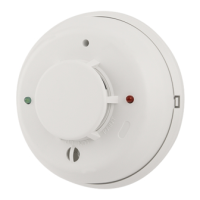
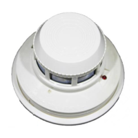
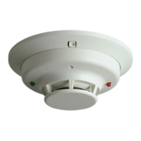
General Description
System Sensor 2400 photoelectronic detectors use state-
of-the-art, optical sensing chambers. These detectors are
designed to provide open area protection, and are intended
for use with compatible UL-listed 2-wire control panels
only. The detector’s operation and sensitivity can be tested
in place. Model 2400TH has the same specifications as
Specifications
Diameter: 5.5 inches (140 mm)
Height: 3.14 inches (80 mm)
Add 0.5 inches (13 mm) for 2400TH
Weight: 0.7 lb. (310 gm)
Operating Temperature Range: Model 2400 — 0° to +49°C (32° to 120°F)
Model 2400TH — 0° to 38°C (32° to 100°F)
Operating Humidity Range: 10% to 93% Relative Humidity Non-condensing
Maximum Air Velocity: 3000 ft/min (15m/s)
Locking Alarm: Reset by momentary power interruption
Electrical Ratings
System Voltage: 12/24 VDC
Maximum Ripple Voltage: 4 Volts peak-to-peak
Start-up Capacitance: 0.02 µF Maximum
Standby Ratings: 8.5 VDC Minimum; 35 VDC Maximum
120 µA Maximum
Alarm Ratings: 4.2 VDC Minimum at 10 mA
6.6 VDC Maximum at 100 mA
Alarm current must be limited to 100mA maximum by the control panel. If used, the
RA400Z Remote Annunciator operates within the specified detector alarm currents.
Reset Voltage: 2.5 VDC Minimum
Reset Time: 0.3 S Maximum
Start-up Time: 34 S Maximum
model 2400, but also features a restorable, built-in, fixed
temperature (135°F) thermal detection unit.
These detectors are listed to UL 268 and are latching type
system detectors. When latched in alarm, the detectors
must be reset by a momentary power interruption.
An LED on the detector provides a local indication of the
detector’s status. This LED blinks every 10 seconds when
the detector is receiving power and ready in standby and
is latched on continuously in alarm until the detector is
reset. The detector provides an output for connection to
an optional Remote Annunciator (Model RA400Z). The
Remote Annunciator mounts to a single gang box and pro-
vides a supplementary alarm indication.
Spacing
NFPA 72E defines the spacing requirements for smoke
detectors, typically 30 feet when detectors are installed on
a smooth ceiling. However, ALL installations must comply
with NFPA 72 and/or special requirements of the authority
having jurisdiction.