Do you have a question about the System Sensor 2112 and is the answer not in the manual?
Details physical dimensions, operating ranges, and alarm features of the smoke detector.
Outlines voltage, current, and timing parameters for the detector's electrical functions.
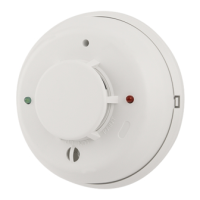
Introduces the 2112/24AITR detector, its sensing technology, and audible alarm features.
Provides essential rules and recommendations for proper wiring of the smoke detector system.
Explains the methods for physically attaching the smoke detector to various electrical boxes.
Details how to activate and use the detector's tamper-resistance mechanism.
Offers guidance on optimal placement for smoke detectors in residential settings.
Lists locations and environmental conditions to avoid for smoke detector installation.
Covers safety warnings and step-by-step instructions for installing the smoke detector.
Describes methods for testing the smoke detector's functionality after installation and maintenance.
Provides instructions for cleaning and maintaining the smoke detector's sensing chamber.
| Model Number | 2112 |
|---|---|
| Type | Photoelectric |
| Voltage | 12 VDC |
| Operating Temperature Range | 32°F to 120°F (0°C to 49°C) |
| Humidity Range | 10% to 93% non-condensing |