Do you have a question about the System Sensor 2412 and is the answer not in the manual?
Details on detector dimensions, operating ranges, electrical ratings, and relay contact specifications.
Guidance on reading manuals and following standards before installing the smoke detectors.
Explanation of the product's technology, LED indicators, and relay functionalities.
Methods for mounting detectors to octagonal and square electrical boxes.
Adherence to codes, wire sizing, loop resistance, and twisted pair recommendations.
Description of the tamper-resistant feature and how to activate/deactivate it.
Important safety warning regarding power disconnection before installation.
Instructions for wiring, mounting, and connecting the smoke detector to the system.
Procedures for notifying authorities and checking detector power before testing.
Methods for testing detector functionality using test switches, cards, modules, or aerosol.
Specific test procedure for the thermal detection unit in TH models.
Procedures for notifying authorities and disabling the system before maintenance.
Steps for removing the cover, cleaning components, and reassembling the detector.
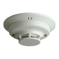
The System Sensor 2412, 2412TH, 2424, and 2424TH are direct wire photoelectronic smoke detectors designed for open area protection. These detectors utilize state-of-the-art optical sensing chambers to detect smoke. They are intended for use with compatible UL-listed 4-wire control panels only. The 2412 models are designed for 12-volt panels and operate at 12VDC, while the 2424 models are for 24-volt panels and operate at 24VDC.
A key feature of these detectors is the integrated LED, which serves as a local alarm indicator. In normal standby mode, the LED flashes every ten seconds to confirm that power is applied to the detector. When the detector enters an alarm condition, the LED illuminates continuously. These detectors also incorporate a latching alarm feature, meaning that once an alarm is triggered, it will remain in the alarm state until a momentary power interruption resets it.
For enhanced fire detection, models 2412TH and 2424TH include a built-in fixed temperature thermal detection unit, which activates at 135°F (57°C). This dual-sensor capability provides an additional layer of protection by responding to both smoke and heat.
Each detector is equipped with two sets of relay contacts: one set of Form A contacts for connection to the alarm-initiating circuit of the control panel, and one set of Form C auxiliary contacts. These contacts operate within specified voltage ratings, allowing for flexible integration into various alarm systems.
System supervision of detector power is achieved by installing a Power Supervisory End-of-Line Relay Module (A77-716 Series) at the end of the detector power loop. When power is supplied to and through the detectors, this EOL Module is energized, causing its relay contacts to close and complete a series circuit in the control panel's alarm-initiating loop. In the event of a power failure or a break in the detector power loop, the EOL Module de-energizes, its relay contacts open, and a trouble signal is triggered at the control panel, ensuring continuous monitoring of the system's integrity.
Installation of these detectors is straightforward. Each unit comes with a mounting bracket kit that allows for direct mounting to 3½-inch or 4-inch octagonal electrical boxes (1½ inches deep), or to a 4-inch square electrical box using a plaster ring. Wiring connections are made by stripping approximately ½ inch of insulation from the wire end, sliding the bare end under the clamping plate, and tightening the screw. It is crucial to follow all wiring guidelines, including using appropriate wire sizes (AWG 18 recommended for signal wiring, up to AWG 12 for screws and clamping plate), color-coding conductors to minimize errors, and adhering to the National Electrical Code and local codes. Twisted pair wiring for the power loop is recommended to reduce electrical interference. For system supervision on terminals 1, 2, 7, and 8, looped wires under terminals should be avoided; instead, the wire run should be broken to provide proper supervision of connections.
A tamper-resistance feature is included to prevent unauthorized removal of the detector without a tool. This is activated by breaking off a smaller tab at the scribed line on the mounting bracket. Once installed, the detector cannot be removed by simply twisting it counterclockwise. To remove a tamper-resistant detector, a small screwdriver must be used to depress the tamper-resistant tab located in the slot on the mounting bracket, allowing the detector to be turned counterclockwise for removal.
Before installation, it is essential to remove power from initiating-device circuits to prevent accidental alarms or damage. After installation, all detectors must be tested to ensure proper operation. This involves applying power to the control unit, then testing each detector.
Several methods are available for testing the detectors:
Detectors that fail these tests should be cleaned and retested. If they continue to fail, they should be returned for repair. After all tests are complete, the proper authorities must be notified that the system is back online.
Maintenance is crucial for ensuring the continued reliability of these smoke detectors. Before performing any maintenance, it is important to notify the proper authorities that the system will be temporarily out of service and to disable the zone or system undergoing maintenance to prevent unwanted alarms.
The cleaning process involves several steps:
Dust covers, provided for limited protection during shipping, must be removed before the smoke detectors can sense smoke. Sensors should also be removed before any heavy remodeling or construction work to prevent damage or contamination. Regular periodic maintenance and testing are essential for the optimal performance of the 2412/2424 series smoke detectors.
| Humidity Range | 0% to 95% RH, non-condensing |
|---|---|
| Type | Photoelectric |
| Power Source | 24V DC |
| Alarm Volume | 85dB at 10 feet |
| Temperature Range | 32°F to 120°F (0°C to 49°C) |
| Compatibility | Compatible with fire alarm control panels |