D400-06-00 2 I56-286-04R
Mounting
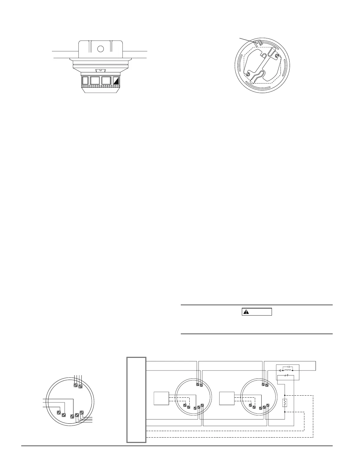
Each 2412 and 2424 detector is supplied with a mounting
bracket kit that permits the detector to be mounted:
1. Directly to a 3
1
⁄2 inch or 4 inch octagonal, 1
1
⁄2 inch deep
electrical box, (see Figure 1) or
2. To a 4 inch square electrical box by using a plaster ring
with the supplied mounting bracket kit.
Installation Wiring Guidelines
NOTE: Refer to releasing device manufacturer’s installa-
tion instruction for proper connections.
All wiring must be installed in compliance with the
National Electrical Code and all applicable local codes and
any special requirements of the authority having jurisdic-
tion, using the proper wire size. The conductors used to
connect smoke detectors to control panels and accessory
devices should be color-coded to reduce the likelihood of
wiring errors. Improper connections can prevent a system
from responding properly in the event of a fire.
For signal wiring (the wiring between interconnected
detectors), it is recommended that the wire be no smaller
than AWG 18. However, the screws and clamping plate, in
the base, can accommodate wire sizes up to AWG 12. The
use of twisted pair wiring for the power (+ and –) loop is
recommended to minimize the effects of electrical interfer-
ence.
Smoke detectors and alarm system control panels have
specifications for allowable loop resistance. Consult the
control panel manufacturer’s specifications for the total
loop resistance allowed for the particular model control
panel being used before wiring the detector loops.
NOTE: For system supervision – for terminals 1, 2, 7, and
8, do not use looped wire under terminals. Break
wire run to provide system supervision of connec-
tions.
NOTE: Contacts are shown in stand-by mode and will
transfer in alarm condition.
Wire connections are made by stripping about
3
⁄8 inch of
insulation from the end of the wire, sliding the bare end of
the wire under the clamping plate, and tightening the
clamping plate screw.
Tamper-resistance Feature
This detector includes a tamper-resistant feature that pre-
vents removal of the detector without the use of a tool. To
make the detector tamper-resistant, break off the smaller
tab at the scribed line on the Tamper Resistant Tab, on the
detector mounting bracket (see Figure 2), then install the
detector. To remove the detector from the bracket once it
has been made tamper-resistant, use a small screwdriver to
depress the tamper-resistant tab located in the slot on the
mounting bracket and turn the detector counterclockwise
for removal.
Installation
Remove power from initiating-device circuits before
installing detectors.