D200-86-00 1 I56-1321-00
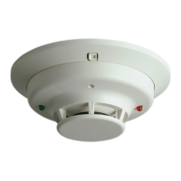
2951 Intelligent Photoelectronic
Smoke Sensor
INSTALLATION AND MAINTENANCE INSTRUCTIONS
A Division of Pittway
3825 Ohio Avenue, St. Charles, Illinois 60174
1-800-SENSOR2, FAX: 630-377-6495
Before Installing
This sensor must be installed in compliance with the con-
trol panel system installation manual. The installation must
meet the requirements of the Authority Having Jurisdiction
(AHJ). Sensors offer maximum performance when installed
in compliance with the National Fire Protection Association
(NFPA); see NFPA 72, and all applicable codes, ordinances
and regulations.
General Description
Model 2951 is a plug-in type smoke sensor that combines a
photoelectronic sensing chamber with addressable-analog
communications. The sensor transmits an analog represen-
tation of smoke density over a communication line to a
control panel. The sensor’s address is set by the Hand Held
Programmer (HHP ). An LED on the sensor is controlled by
the panel to indicate sensor status.
The Model 2951 requires compatible addressable com-
munications to function properly. Connect this sensor to
listed-compatible control panels only.
Spacing
System Sensor recommends spacing sensors in compliance
with NFPA 72. In low air flow applications with smooth
ceilings, space sensors 30 feet apart. For specific informa-
tion regarding sensor spacing, placement, and special ap-
plications, refer to NFPA 72 or the System Sensor Guide For
Proper Use of System Smoke Detectors, available at no
charge from System Sensor (P/N I56-407-XX).
Specifications
Operating Voltage Range: 15 to 30 VDC
Current: 270
µ
A Max. Communication active but not to device in blink mode
LED Current: 6.5 mA Continous ON
Operating Humidity Range: 10% to 93% Relative Humidity, noncondensing
Operating Temperature Range: 0° to 49°C (32° to 120°F)
Height: 1.95 inches (50 mm) installed in Base
Diameter: 4.0 inches (102 mm) installed in Base
Weight: 2.96 oz. (92 g)
Wiring Instructions
All wiring must be installed in compliance with the Na-
tional Electrical Code, applicable local codes, and any spe-
cial requirements of the Authority Having Jurisdiction.
Proper wire gauges should be used. The installation wires
should be color-coded to limit wiring mistakes and ease
system troubleshooting. Improper connections will prevent
a system from responding properly in the event of a fire.
NOTE: The mounting base (B901) uses SEMS Plate termi-
nals and can accommodate 2 wires each. The 2
wires can differ by a maximum of 2 wire gauges.
Remove power from the communication line before in-
stalling sensors.
All wiring must conform to applicable local codes, ordi-
nances, and regulations.
1. Wire the sensor base (supplied separately) per the wir-
ing diagram, see Figure 1.
2. Prior to installation, address the sensor using the Hand
Held Programmer (HHP ). See Hand Held Programmer
instruction manual for proper operation.
3. Install the sensor into the sensor base. Push the sensor
into the base while turning it clockwise to secure it in
place.