D100-04-00 3 I56-1015-000
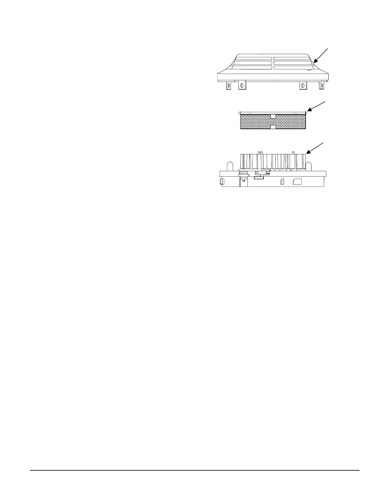
Figure 2:
A78-2456-00
B. Test Module ( MOD400R)
Use the MOD400R with a DMM or voltmeter to check
the detector sensitivity as described in the MOD400R
manual.
C. Aerosol Generator (Gemini 501)
Set the generator to represent 4% to 5%/ft. obscura-
tion as described in the Gemini 501 Manual. Using the
bowl- shaped applicator, apply aerosol until unit alarms.
Notify the proper authorities that the system is back on
line.
Detectors that fail these tests should be cleaned as
described under MAINTENANCE and retested. If the
detectors still fail these tests, they should be returned for
repair.
Maintenance
It is recommended that the detector be removed from
its mounting base to facilitate cleaning. The detector is
cleaned as follows:
NOTE: Before removing the detector, notify the proper
authorities that the smoke detector system is
undergoing maintenance and will be temporarily
out of service. Disable the zone or system under-
going maintenance to prevent unwanted alarms.
1. Remove the detector cover by prying away the four
side tabs with a small-bladed screwdriver, and then
pulling the cover from the base.
2. Vacuum the screen carefully without removing it. If
further cleaning is required continue with Step 3, oth-
erwise skip to Step 6.
3. Remove the screen assembly by pulling it straight out
(see Figure 2). Vacuum the inside.
4. Clean the vaned chamber piece by vacuuming or blow-
ing out dust and particles.
5. To replace the screen, orient it so that the arrow on top
aligns with the arrow on the printed circuit board. Care-
fully push the screen assembly onto the vaned cham-
ber making sure it ts tightly.
6. Replace the cover by gently pushing it until it locks in
place.
7. Reinstall the detector.
8. Notify the proper authorities that the system is back on
line.
REMOVABLE
COVER
VANED
CHAMBER
REMOVABLE
SCREEN