Do you have a question about the System Sensor 2300TB and is the answer not in the manual?
Overview of the 2300TB as a 2-wire smoke/heat detector with electronic thermistors.
Lists diameter, height, operating temperature, humidity, and sensitivity.
Details voltage, current, ripple voltage, and capacitance requirements.
Describes how to mount the detector to various electrical boxes.
Explains how to enable and bypass the tamper-resistant capability.
Provides recommendations for wire gauge, conduit, and connections.
Step-by-step instructions for wiring and securing the detector.
Details how to test smoke and heat detection using various methods.
Instructions for removing the detector, cleaning, and reinstallation.
Discusses detector limitations, environmental factors, and lifespan.
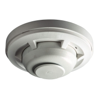
The Model 2300TB is a 2-wire combination smoke/heat detector designed for fire detection systems. It integrates both photoelectronic smoke detection and heat detection capabilities, making it a versatile device for open area protection. The heat detection feature is provided by two supervised electronic thermistors that trigger an alarm at a fixed temperature of 135°F. This detector is designed to be used with UL-listed compatible 2-wire control panels.
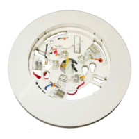
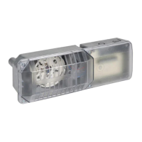
One of the key usage features of the 2300TB is its simplified installation process. It comes with an adaptor bracket and a plug-in screw terminal block. The screw terminal block can be pre-wired to the system, allowing for easy installation or removal of the detector, which is particularly convenient for cleaning or maintenance. The detector is listed to UL 268 standards, ensuring its compliance with safety and performance requirements.
The 2300TB operates as a latching type system detector. This means that once it goes into an alarm state, it will remain latched in alarm until it is manually reset. Resetting the detector requires a momentary power interruption to the device. This feature helps ensure that an alarm condition is acknowledged and addressed before the system returns to normal operation.
For local status indication, the detector is equipped with an LED. This LED provides clear visual feedback on the detector's operational status. When power is applied and the detector is functioning correctly in standby mode, the status LED will blink approximately every 10 seconds. The detector also performs a self-test of its smoke sensing chamber and internal electronics every 40 seconds. If this self-test fails, the LED will stop blinking and remain off, indicating a potential issue with the unit. In an alarm condition, the LED will be continuously lit until the detector is reset, providing an immediate visual alert of a fire event.
The detector's sensitivity can be tested in place using the MOD400R field sensitivity test module. This allows for convenient verification of the detector's performance without needing to remove it from its installed location.
The 2300TB also offers an output for connecting an optional Remote Annunciator, specifically the model RA400Z. This accessory mounts to a single gang box and provides an additional LED indication of an alarm condition, which can be useful for remote monitoring in larger installations or areas where the detector's LED might not be easily visible.
The mounting bracket supplied with each 2300TB detector allows for flexible installation options. It can be mounted to a single gang box, directly to a 3-1/2 inch or 4-inch octagonal box, or to a 4-inch square electrical box using a plaster ring. This adaptability ensures that the detector can be integrated into various electrical box configurations commonly found in buildings.
A tamper-resistant capability is integrated into the detector to prevent unauthorized removal from its bracket without the use of a tool. To activate this feature, a smaller tab on the detector mounting bracket needs to be broken off at a scribed line before installation. To remove a tamper-resistant detector, a pocket screwdriver or similar tool must be used to depress the tamper-resistant tab, which is accessible through a slot on the mounting bracket, and then the detector can be turned counterclockwise.
For wiring, the screw terminal block accepts 14-22 gauge wire. It is crucial that all wiring complies with the National Electrical Code, applicable local codes, and any special requirements of the local authority having jurisdiction. Color-coded conductors are recommended to minimize wiring errors. For optimal system performance, wiring should be installed in separate grounded conduit, and fire system wiring should not be mixed with other electrical wiring in the same conduit. Twisted pair wiring can provide additional protection against extraneous electrical interference. Wire connections are made by stripping about 1/4 inch of insulation, inserting the wire into the appropriate terminal, and tightening the screw.
Maintenance of the 2300TB detector is important for ensuring its continued proper operation. Before any maintenance or removal, it is essential to notify the proper authorities that the smoke detector system will be temporarily out of service and to disable the zone or system to prevent unwanted alarms. If removing a detector from a system with more than one detector per loop, an optional detector bypass plug (model J2300TB) can be inserted into the screw terminal block to maintain system continuity.
When cleaning the detector, the cover can be removed by inserting a small-bladed screwdriver into the cover removal slot and twisting it slightly, then turning the cover counterclockwise. It's important to note the position of the thermistors before removing the cover and to ensure they are seated and not bent when the cover is replaced. After removing the cover, the screen can be pulled straight out. Care must be taken not to damage the thermistors during this step. The screen should be thoroughly vacuumed. The black vaned chamber piece, which is crucial for smoke sensing, should also be cleaned by vacuuming or blowing out dust and particles. To re-install the screen, it should be rotated on the housing until it drops into the alignment slots, then carefully pushed onto the base to ensure a tight fit to the chamber. Replacement screens are available (part number RS23). Finally, the cover is replaced by gently rotating it clockwise until it locks in place, again ensuring the thermistors are in an upright position. After reinstallation, the system should be enabled, and authorities notified that it is back online.
Regular testing is also a key part of maintenance. Detectors must be tested after installation and periodically thereafter. Before testing, authorities should be notified, and the zone or system disabled to prevent unwanted alarms. The presence of the flashing LED indicates proper power and function; if it's not flashing, power should be checked, or the unit may be defective. Testing can be performed using several methods:
Both smoke and heat detection testing are recommended to verify system protection. If a detector fails to activate after these tests, it should first be cleaned as outlined in the maintenance section. If it still fails, it should be returned for repair.
It is important to remember that smoke detectors have limitations. They are designed to activate and initiate emergency action only when used with an authorized fire alarm system and must be installed according to NFPA standard 72. They require power to operate and will not function if the power supply is cut off. Smoke detectors may not sense fires that start where smoke cannot reach them, such as in chimneys, walls, or behind closed doors. They may also have delays in detecting smoldering fires, which produce less heat to drive smoke to the ceiling. Detectors cannot detect fires on other levels of a building quickly or at all, emphasizing the need for detectors on every level and in every bedroom.
Different types of detectors have varying sensing capabilities; ionization detectors are generally better at detecting fast flaming fires, while photoelectric detectors are better at sensing slow smoldering fires. Since fires develop unpredictably, no single type of detector is always best, and a given detector may not always provide early warning for a specific fire type.
Detectors are not designed to provide warnings for fires resulting from inadequate fire protection practices, violent explosions, escaping gases, improper storage of flammable liquids, arson, or other similar safety hazards. High air velocity conditions can dilute smoke densities, potentially delaying alarms, and may increase dust contamination, requiring more frequent maintenance.
Finally, smoke detectors contain electronic parts and do not last forever. Even though they are designed for over 10 years, any part can fail at any time. Therefore, smoke detectors should be replaced after 10 years of service. The system must be tested regularly per NFPA 72, and the detector should be cleaned regularly, at least once a year.
| Operating Voltage Range | 8.5 to 35 VDC |
|---|---|
| Thermal Sensor | Yes |
| Fixed Temperature Threshold | 135°F (57°C) |
| Color | White |
| Maximum Alarm Current | 130 mA |
| Operating Temperature Range | 0° to 49°C (32° to 120°F) |
| Operating Humidity Range | 10% to 93% non-condensing |
| Height (including base) | 2.0 inches (51 mm) |
| Diameter | 4.0 in (102 mm) |
| Weight | 3.5 oz (99 g) |
| Agency Listings | UL, ULC, CSFM, MEA, FM |
| Humidity Range | 10% to 93% non-condensing |
| Dimensions | 4.0 in (102 mm) diameter, 2.0 in (51 mm) height |
| Type | Photoelectric Smoke Detector with Thermal Sensor |