EasyManua.ls Logo

System Sensor CO1224 - User Manual

System Sensor CO1224
4 pages
To Next Page IconTo Next Page
Loading...
D250-03-00 1 I56-2874-001
CO1224
Carbon Monoxide Detector
INSTALLATION AND MAINTENANCE INSTRUCTIONS
3825 Ohio Avenue, St. Charles, Illinois 60174
1-800-SENSOR2, FAX: 630-377-6495
www.systemsensor.com
NOTICE: This manual shall be left with the owner/user of
this equipment.
WARNING: This product is intended for use in ordinary indoor
locations of dwelling units, including homes, residential buildings,
hotels, schools, dormitories, and day care centers. It is not intended
for use in industrial factories or commercial parking garages.
General Description
Listed to UL standard 2075
4 wire, system monitored
Local sounder
Low current draw
Alarm relay, Form C
Trouble relay, Form A
Dual LED’s
Test/Hush button
SEMS wiring terminals
Mount to single gang electrical box or surface mount to wall
or ceiling
Optional drywall anchors included
Figure 1. Alarm Location Diagram:
Specifications
Electrical Specifications
System Voltage
Nominal: 12/24 VDC
Min: 10 VDC
Max: 33 VDC
Avg. Standby Current: 20 mA
Max Alarm Current: 40 mA (75 mA test)
Alarm Contact Ratings: 30 VDC @ 0.5 A
Trouble Contact Ratings: 30 VDC @ 0.5 A
Audible Signal (temp 4 tone): 85 dBA min. in alarm (at 10ft)
Max. Start-up Capacitance: 20 uF
Physical Specifications
Operating Temperature Range: 0
° to 40°C (32° to 104°F)
Operating Humidity Range: 22 – 90% %RH
Length: 5.1˝
Width: 3.3˝
Height: 1.3˝
Weight: 7 oz
Wire Gauge Acceptance: 14-22 AWG
Table 1. Detector Operation Modes:
Operation
Mode
Green
LED
Red
LED
Sounder
Normal
(standby)
Blink 1
per minute
- -
Alarm -
Blink in
temp 4*
pattern
Sound in
temp 4*
pattern
*Temp 4 pattern is repeated pattern of four short indications fol-
lowed by a five second pause.
When the detector has been in alarm for 30 minutes the alarm
signal will be given once every minute.
If ambient conditions return to normal, the detector will self-re
-
store out of alarm and into Normal (standby) mode.
Hush feature: If required, the audible alarm can be silenced for
5 minutes by pushing the button marked “Test/Hush”. The red
alarm light will continue to flash in temp-4 pattern. If carbon
monoxide is still present after the 5 minute hush period, the au
-
dible alarm will sound. The hush facility will not operate at levels
above 350 ppm (parts per million) carbon monoxide.
Trouble feature: When the sensor supervision is in a trouble con-
dition (such as a sensor that has been tampered with), the detec
-
tor will send a trouble signal to the panel. The detector must then
be replaced.
End of Life Timer feature: When the detector has reached the
end of its life, the trouble contact will open. This indicates that
the CO sensor inside the detector has passed the end of its life
and must be replaced. This detector’s lifespan is approximately
six years from the date of manufacture. Refer to Detector Replace
-
ment on page 3.
Per UL 2075, it is mandatory that a trouble signal be sent to the
panel upon CO cell trouble or cell end of life. Refer to Figure 4
for wiring of the trouble relay.
LIVING
ROOM
BEDROOM BEDROOM
BEDROOM
KITCHEN
TO
BR
CLOSED
DOOR
BASEMENT
GARAGE
CARBON MONOXIDE ALARM
LOCATION FOR MULTI-LEVEL RESIDENCE
C0295-00
Question and Answer IconNeed help?

Do you have a question about the System Sensor CO1224 and is the answer not in the manual?

System Sensor CO1224 Specifications

General IconGeneral
TypeCarbon Monoxide Detector
Standby Current100 µA
Alarm Current50 mA
Sensor TypeElectrochemical
Power Supply12-24 VDC
Temperature Range0 to 49 °C
Humidity Range10% to 93% RH, non-condensing
Sounder85 dBA at 10 ft (3 m) minimum
ListingsUL
Alarm IndicationLED

Summary

Detector Specifications

Electrical Specifications

Details electrical parameters including system voltage, current draw, and contact ratings.

Physical Specifications

Details physical attributes such as operating temperature, humidity, dimensions, and weight.

General Description and Operation Modes

General Description

Outlines key features, certifications, and general characteristics of the CO1224 detector.

Detector Operation Modes

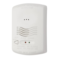
Explains the detector's behavior with LED indicators and sounder in normal and alarm states.

Hush and Trouble Features

Describes the hush function for temporary alarm silencing and the trouble signal for sensor issues.

End of Life Timer

Details the detector's lifespan and how the trouble contact signals the end of its useful life.

Installation and Wiring

Installation Guidelines

Provides recommendations for ideal and non-ideal detector placement locations.

Mounting Options

Explains how to mount the detector to electrical boxes or directly to surfaces.

Wiring and Installation Procedure

Covers wiring requirements, safety precautions, and step-by-step installation instructions.

Testing, Safety, and Maintenance

Testing Procedure

Details the steps to verify detector functionality after installation.

Test Button Operation

Explains how to use the test button and interpret its feedback for verification.

Safety Precautions and Limitations

Highlights essential safety warnings, limitations, and what the detector is not designed for.

Maintenance and Replacement

Provides instructions for cleaning, care, and timely replacement of the detector.

Wiring Diagrams

Single Unit Wiring

Illustrates wiring diagrams for a single CO1224 detector connection.

Multiple Unit Wiring

Illustrates wiring diagrams for connecting multiple CO1224 detectors to a zone.

Installation Caution

Provides specific cautions related to the installation and wiring of the CO1224.

Related product manuals