D100-101-00C 1 I56-6476-000
INSTALLATION AND MAINTENANCE INSTRUCTIONS
Model 885-WP
Weatherproof
Heat Detector
SPECIFICATIONS
Diameter:
Height (including mounting bracket):
Weight (including mounting bracket):
Operating Temperature Range:
IP Rating:
Sensitivity:
Operating Voltage:
Standby Current:
Alarm Current:
Latching Alarm:
Software Ver.
Standard:
Type:
102.5 mm (4.04 inches)
47.5 mm (1.87 inches)
142 g (5.0 ounce)
-10°C to 50°C (14°F to 122°F)
IP66
60°C (140°F) Fixed Temperature with Rate-of-Rise
8.5VDC to 35VDC
≤140μA
10mA ~130mA (Controlled by panel and current limiting resistor)
≤5s
A
AS 7240.5―2004
A2R
BEFORE INSTALLING
Please thoroughly read System Sensor manual which provides detailed
information on detector spacing, placement, zoning, wiring, and special
applications. Copies of this manual are available at no charge from System
Sensor.
NOTICE: This manual shall be left with the owner/user of this equipment.
IMPORTANT: This detector must be tested and maintained regularly in
accordance with the requirements of the local standards and regulations.
The detector should be cleaned at least once a year.
GENERAL D
ESCRIPTION
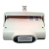
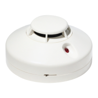
Model 885-WP is a 2-wire rate-of-rise with fixed temperature (60°C) heat
detector. This detector is designed to provide open area protection in areas
subject to moisture. This detector is sealed against the entry of moisture to
a rating of IP66. The LED will latch on when the detector is in alarm.
MOUNTING
Each 885-WP detector is supplied with a mounting bracket that permits the
detector to be mounted directly to the ceiling or to a junction box.
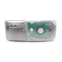
Tamper-resistant Feature
This detector includes a tamper-resistant feature that prevents its removal
from the mounting bracket without the use of a key. To make the detector
tamper-resistant, remove the tab from the tamper arm on the mounting
bracket using a cutting tool. Remove the tamper key from the center of the
mounting bracket by twisting it back and forth several times (see Figure2).
Once the detector is installed, it may be removed from the mounting
bracket by inserting the T-shaped end of the key into the slot on the side of
the unit and rotating the detector counter-clockwise.
Figure1.
Surface mounting of the 885-WP
weatherproof
heat detector into a 50/60 mm
junction box.
NOTE: Please dispose electronic waste following national or local regulations
after being scrapped or replaced. Do not discard.
Figure2.
Module 885-WP weatherproof Heat
Detector
Mounting bracket
Wiring Installation Guidelines
This detector provides six wires which are divided into three groups,
separately two red, two white and two black wires. Refer to Figure 4.
Terminal Notes:
Red wire: Power / Detector Circuit +ve
Black wire Power / Detector Circuit -ve
(the power and the LED use the same cathode)
White wire Remote LED +ve
Wiring Diagram refers to Figure 4.
Remove power from the communication line before installing detector.
1. Connect the wires to power wiring as per the wiring diagram, see
Figure 4.
2. The wiring connections must be prevented from water, see figure 3.
INSTALLATION
NOTE: All wiring must conform to applicable local codes, ordinances, and
regulations.
NOTE: Verify that all detector mounting brackets are installed, that the
initiating-device circuits have been tested, and that the wiring is correct.
Remove power from initiating-device cir
cuits before installing
detectors
.
1. Secure mounting
bracket to the roof or ceiling.
2. Push the detector into the mounting bracket while turning it
clockwise to secure it into place. Connect the wires to power wiring
in junction box, see Figure 3.
3. After all detectors have been installed, apply power to the control unit
or initiating-device circuits.
I56-6476-000
A5665‐112
TAMPER KEY
ALIGNMENT
NOTCHES
TAMPER ARM
(CUT OFF SMALL TAB TO ACTUATE
TAMPER-RESIST FEATURE-DEPRESS
ARM WITH KEY TO REMOVE DETECTOR)
A5665‐113
WARNING
mounted onto the mounting bracket
the detectorhenwentmAlign