D770-01-00 1 I56-459-07
WFD Vane-type Waterflow
Detectors
INSTALLATION AND MAINTENANCE INSTRUCTIONS
A Division of Pittway
3825 Ohio Avenue, St. Charles, Illinois 60174
1-800-SENSOR2, FAX: 630-377-6495
Important
Please Read Carefully And Save
This instruction manual contains important information
about the installation and operation of waterflow detectors.
Purchasers who install waterflow detectors for use by oth-
ers must leave this manual or a copy of it with the user.
Read all instructions carefully before beginning. Follow
only those instructions that apply to the model you are in-
stalling.
CAUTION
Use vane-type waterflow detectors in wet-pipe systems
only. Do NOT use them in dry pipe, deluge, or preaction
systems. The sudden inrush of water in such systems may
break the vane or damage the mechanism.
Do not use in potentially explosive atmospheres. Do not al-
low unused wires to remain exposed.
Specifications
Contact Ratings: 10 A @ 125/250 VAC
2.5 A @ 24 VDC
Triggering Threshold Bandwidth (Flow Rate): 4 to 10 gpm
Static Pressure Rating: 250 PSI (Max) 2" – 8"
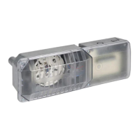
Dimensions, Installed: 3.5"H x 3.0"W x 6.7"D
Operating Temperature Range: 32°F to 120°F (0°C to 49°C)
Compatible Pipe: Steel water pipe, schedule 10 or 40.
Shipping Weight: 4 to 7 lb., according to size.
Enclosure Rating: NEMA 4, as tested by Underwriters Laboratories, Inc.
(requires optional Outdoor Cover Gasket Model WFDN4 and cover part #C58-164-01)
Principles Of Operation
Vane-type waterflow detectors mount to water-filled pipes
in sprinkler systems. Waterflow in the pipe deflects a vane,
which produces a switched output–usually after a specified
delay. All waterflow detectors have a pneumatically con-
trolled mechanical delay mechanism. Delays do NOT accu-
mulate; they reset if the flow of water stops before the
entire delay has elapsed. All switches actuate when the wa-
ter flow rate is 10 gallons per minute or greater, but will not
actuate if the flow rate is less than 4 gallons per minute.
This System Sensor installation manual covers the follow-
ing waterflow detectors for sprinkler/fire alarm applica-
tions.
Models
WFD20 Waterflow detector, Schedule 10/40, 2"
WFD25 Waterflow detector, Schedule 10/40, 2-1/2"
WFD30 Waterflow detector, Schedule 10/40, 3"
WFD35 Waterflow detector, Schedule 10/40, 3-1/2"
WFD40 Waterflow detector. Schedule 10/40, 4"
WFD50 Waterflow detector, Schedule 10/40, 5"
WFD60 Waterflow detector, Schedule 10/40, 6"
WFD80 Waterflow detector, Schedule 10/40, 8"
Technical Manuals Online! - http://www.tech-man.com