INSTALLATION AND MAINTENANCE INSTRUCTIONS
3825 Ohio Avenue, St. Charles, Illinois 60174
1-800-SENSOR2, FAX: 630-377-6495
www.systemsensor.com/www.systemsensor.ca
BEFORE INSTALLING
Please read the System Smoke Detectors Application Guide, which provides
detailed information on detector spacing, placement, zoning, wiring, and spe-
cial applications. Copies of this application guide are available from System
Sensor. Observe guidelines for NFPA 72 or CAN/ULC S524 (depending on
location).
NOTICE: This manual should be left with the owner/user of this equipment.
IMPORTANT: Use only with compatible ULC-listed detector heads for proper
system function. The detector used with this base must be tested and main-
tained regularly following requirements of NFPA 72 or CAN/ULC S536 (de-
pending on location). The detector should be cleaned at least once a year.
IMPORTANT: Utiliser uniquement avec des détecteurs homologuées ULC
pour le bon fonctionnement du système. Le détecteur utilisé avec cette base
doit être testé et entretenu régulièrement en conformité avec les exigences de
la norme CAN/ULC S536. Le détecteur doit être nettoyé au moins une fois
par an.
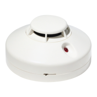
GENERAL DESCRIPTION
The B501-WHITE, B501-IV, and B501-BL are plug in detector bases intended
for use in an intelligent system with screw terminals provided for power
(+ and –), and remote annunciator connections. Communication takes place
over the power lines (+ and –).
BASE TERMINALS
No. Function
1 Power (–), Remote Annunciator (–)
2 Power (+)
3 Remote Annunciator (+)
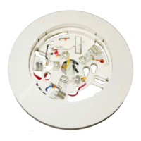
FIGURE 1. TERMINAL LAYOUT
TAB
TERMINAL 3
TERMINAL 2
TERMINAL 1
C0131-01
SPECIFICATIONS
Base Diameter: 4.0" (10.2 cm)
Base Height: 0.74" (18.8 mm)
Operating Temperature: Refer to applicable sensor Operating Temperature Range using the Base/Sensor Cross Reference Chart at systemsensor.com
Electrical Ratings – includes base and detector
Operating Voltage: 15 to 32 VDC
Standby Current: 150 µA
Listings: UL268, ULC S529
I56-3738-004
MOUNTING
This detector base mounts directly to 4" square with plaster ring, 3
1
/2" octa-
gon, 50 mm, 60 mm, and 70 mm centers.
INSTALLATION AND WIRING GUIDELINES (SEE FIGURE 2)
All wiring must be installed in compliance with all applicable local codes
and any special requirements of the local authority having jurisdiction. Proper
wire gauges should be used. The conductors used to connect smoke detectors
to control panels and accessory devices should be color-coded to reduce the
likelihood of wiring errors. Improper connections can prevent a system from
responding properly in the event of a fire.
For signal wiring (the wiring between interconnected detectors and modules),
it is recommended that the wiring be no smaller than 18 AWG (0.823 mm²).
Wire sizes up to 12 AWG (3.31 mm²) may be used with the base.
Alarm system control panels have specifications for allowable loop resistance.
Consult the control panel specifications for the total loop resistance allowed
before wiring the detector loops.
Make wiring connections by stripping about
3
/8" (10 mm) of insulation from
the wire end (use strip gauge molded in base). Then slide the wire under the
clamping plate and tighten the clamping plate screw. Do not loop the wire
under the clamping plate. (See Figure 3.)
Check the zone wiring of all bases in the system before installing the detec-
tors. This includes checking the wiring for continuity, correct polarity, ground
fault testing and performing a dielectric test.
The base includes an area for recording the zone, address, and type of detec-
tor to be installed at that location. This information is useful for setting the
detector head address and for verification of the detector type required for
that location.
Once all detector bases have been wired and mounted, and the loop wiring
has been checked, the detector heads may be installed in the bases.
FIGURE 2. TYPICAL WIRING DIAGRAM FOR 2-WIRE LOOP
(–)
(+)
+ -
Control Panel
CAUTION: Do not loop wire under terminal 1 or 2. Break wire run to
provide supervision of connections.
MISE EN GARDE : Ne pas boucler le fil sous la borne 1 ou 2.
Couper le fil pour assurer la supervision des connexions.
CLASS A OPTIONAL WIRING
REMOTE
ANNUNCIATOR
(–)
(+)
3
2
1
3
2
1
3
2
1
C0133-03
B501-WHITE, B501-IV, and B501-BL
4" Plug-in Detector Bases
1 I56-3738-004
03/07/2018