EasyManua.ls Logo

System Sensor PC2RLED - User Manual

System Sensor PC2RLED
11 pages
Print Icon
To Next Page IconTo Next Page
Loading...
I56-0022-000
INSTALLATION AND MAINTENANCE INSTRUCTIONS
ENGLISH
L-Series with LED
Indoor Selectable-Output
Horn Strobes and Strobes
3825 Ohio Avenue, St. Charles, Illinois 60174
800/736-7672, FAX: 630/377-6495
www.systemsensor.com
LED L-series Indoor Horn Strobes and Strobes — P/N I56-0022-000 8/25/2023 1
Manual is for use with the following models:
Horn Strobes
Standard Wall Mount Horn Strobes: P2RLED, P2RLED-B, P2WLED, P2WLED-B, P2RLED-P, P2WLED-P, P2RLED-SP, P2WLED-SP
Compact Wall Mount Horn Strobes: P2GRLED, P2GRLED-B, P2GWLED, P2GWLED-B
Standard Ceiling Mount Horn Strobes: PC2RLED, PC2RLED-B, PC2WLED, PC2WLED-B
2-Wire Strobes
Standard Wall Mount Strobes: SRLED, SRLED-B, SWLED, SWLED-B, SRLED-P, SWLED-P, SRLED-SP, SWLED-CLR-ALERT, SWLED-ALERT*
Compact Wall Mount Strobes: SGRLED, SGRLED-B, SGWLED, SGWLED-B
Ceiling Mount Strobes: SCRLED, SCRLED-B, SCWLED, SCWLED-B, SCWLED-CLR-ALERT, SCRLED-P, SCWLED-P
Language designators: “-B” are bilingual (English/French). “-P” are plain versions (no wording). “-SP” are marked “FUEGO”
*Amber lenses are for use in UL applications.
Table of Contents
Section 1: Introduction .................................................................................................................................................. 2
1.1 Product Specifications .......................................................................................................................................................2
1.2 Dimensions and Mounting Options ...................................................................................................................................2
1.3 Before Installing ................................................................................................................................................................2
1.4 General Description ..........................................................................................................................................................2
1.5 Fire Alarm System Considerations ....................................................................................................................................3
1.6 System Design ..................................................................................................................................................................3
Section 2: Configurations for Notification Appliances ............................................................................................... 4
2.1 Available Tones .................................................................................................................................................................4
2.2 Available Candela Settings ...............................................................................................................................................4
2.3 Current Draw and Audibility ratings ...................................................................................................................................5
Section 3: Installation .................................................................................................................................................... 7
3.1 Wiring and Mounting .........................................................................................................................................................7
3.2 Wiring Diagrams ................................................................................................................................................................7
3.3 Install Back Box .................................................................................................................................................................7
3.4 Install Mounting Plate and Appliance ................................................................................................................................7
3.5 Remove a Ceiling Model Appliance ..................................................................................................................................8
3.5.1 Mounting Drawings ........................................................................................................................................................8
3.6 Tamper Screw .................................................................................................................................................................10
3.7 Test Points ......................................................................................................................................................................10
Question and Answer IconNeed help?

Do you have a question about the System Sensor PC2RLED and is the answer not in the manual?

Summary

Section 1: Introduction

Product Specifications

Detailed electrical and physical specifications for the horn strobes and strobes.

Dimensions and Mounting Options

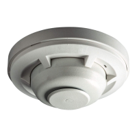
Provides physical dimensions and compatible mounting configurations for wall and ceiling units.

Before Installing

Guidance on pre-installation requirements and references to codes and guides.

General Description

Overview of System Sensor notification appliances and their intended applications.

Fire Alarm System Considerations

Requirements for temporal coded signals and compliance with fire alarm codes.

System Design

Guidelines for system designers regarding current draw and voltage drop calculations.

Section 2: Configurations for Notification Appliances

Available Tones

Describes the selectable tone patterns and volume settings for horn activation.

Available Candela Settings

Details the selectable candela settings for strobe light output and verification.

Current Draw and Audibility Ratings

Tables detailing current draw and sound output for various settings and candela ratings.

Section 3: Installation

Wiring and Mounting

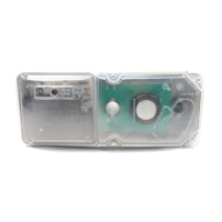
Instructions for proper wiring connections and physical mounting of the devices.

Wiring Diagrams

Visual representations of system wiring for 2-wire horn strobes and strobes.

Install Back Box

Procedures for attaching the required back box to walls or ceilings.

Install Mounting Plate and Appliance

Steps for attaching the mounting plate and securing the appliance to it.

Remove Ceiling Model Appliance

Instructions specific to removing ceiling-mounted appliance models.

Tamper Screw

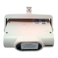
Information on the tamper-resistant screw and its replacement.

Test Points

Location and usage of diagnostic test points for voltage measurement.

Overview

This document provides installation and maintenance instructions for the System Sensor L-Series with LED Indoor Selectable-Output Horn Strobes and Strobes. These devices are designed for life safety notification in indoor applications and are available in standard and compact versions for both wall and ceiling mounts.

Function Description:

The L-Series devices serve as public mode notification appliances, alerting occupants to a life safety event through both audible (horn) and visible (strobe) signals. Two-wire horn strobes and strobes are listed to ANSI/UL 464/ULC-S525 (horn) and ANSI/UL 1638/ULC-S526 (strobe) requirements. Additionally, two-wire amber ALERT strobes are available as private mode notification appliances, intended to alert trained personnel to investigate a life safety event, and are listed to ANSI/UL 1638 (Private mode) for UL applications (not listed for Canadian applications).

These devices are designed for use in 24VDC systems and can be activated by a compatible fire alarm control panel or power supply. They come enabled with System Sensor synchronization protocol, requiring connection to a power supply capable of generating synchronization pulses, a FACP NAC output configured to System Sensor synchronization protocol, or the use of a synchronization module. System Sensor wall 2-wire horn strobes and strobes are electrically backward compatible with previous generations of notification appliances.

Important Technical Specifications:

  • Operating Temperature: 32°F to 120°F (0°C to 49°C)
  • Humidity Range: 10 to 93% Non-condensing
  • Strobe Flash Rate: 1 flash per second
  • Nominal Voltage: Regulated 24 VDC
  • Operating Voltage Range: 16 to 33V (24V nominal)
  • Input Terminal Wire Gauge: 12 to 18 AWG
  • Dimensions (Standard Wall Mount): Length 5.67" (144 mm), Width 4.7" (119.4 mm), Depth 2.07" (52.6 mm)
  • Dimensions (Compact Wall Mount): Length 5.27" (133.7 mm), Width 3.45" (87.8 mm), Depth 2.07" (52.6 mm)
  • Dimensions (Standard Ceiling Mount): Diameter 6.83" (173.5 mm), Depth 2.07" (52.6 mm)
  • Mounting Options:
    • Standard 2-Wire Indoor Products: 4" x 4" x 1½", Single Gang, Double Gang, 4" Octagon, SBBRL/WL (wall), SBBGRL/WL (wall)
    • Compact 2-Wire Indoor Products: Single Gang, SBBGRL/WL (wall)
    • Ceiling Mounted Products: 4" x 4" x 1½", Single Gang, Double Gang, 4" Octagon, SBBCRL/WL (ceiling)

Usage Features:

  • Selectable Output: The devices offer 8 field-selectable tone and volume combinations for the horn, and 7 field-selectable candela settings for the strobe.
  • Tone Selection: Tones are selected using a rotary switch on the back of the product. Available tones include Temporal 3 (high/low volume), Non-Temporal (high/low volume), 3.1 KHz Temporal 3 (high/low volume), and 3.1 KHz Non-Temporal (high/low volume). The Temporal 3 pattern complies with ANSI and NFPA 72 for standard emergency evacuation signaling.
  • Candela Setting: Candela output is selected via a rotary switch on the back of the product. The setting can be verified through a small window on the front of the unit. Available candela ratings for wall mounts include 15, 30, 75, 95, 110, 135, 185 cd, and FCP (future). For ceiling mounts, 15, 30, 75, 95, 115, 150, 177 cd, and FCP (future) are available.
  • Wiring and Mounting: All wiring must comply with National Electric Code (UL applications), Canadian Electric Code (ULC applications), and local codes. Wire sizes up to 12 AWG (2.5 mm²) can be used with the mounting plate.
  • Shorting Spring Feature: The mounting plate includes a shorting spring between terminals 2 and 3, enabling system continuity checks of field wiring before appliances are installed. This spring automatically disengages when the product is installed, facilitating supervision of the final system.
  • Back Box Installation: Junction boxes are mounted per industry standards. Surface mount back boxes can be secured directly to the wall or ceiling, with optional use of a grounding bracket. Specific mounting holes are designated for ceiling horn strobes/strobes (STR) and speakers/speaker strobes (SPK).
  • Knockouts: Threaded knockouts are provided for 3/4 inch and 1/2 inch conduit adapters. Rear entry knockouts for 3/4 inch and 1/2 inch are also available. V500 and V700 raceway knockouts are provided for low and high profile applications, respectively.
  • Mounting Plate and Appliance Installation: The mounting plate is attached using Philips head screws. The appliance hooks onto grooves on the mounting plate and is secured with a single mounting screw.
  • Language Designators: Models with "-B" are bilingual (English/French), "-P" are plain versions (no wording), and "-SP" are marked "FUEGO". Amber lenses are for use in UL applications.

Maintenance Features:

  • Testing and Maintenance: The notification appliance must be tested and maintained according to NFPA 72 requirements for UL applications or CAN/ULC S536 for ULC applications.
  • Tamper Screw: For tamper resistance, the standard captive screw can be replaced with a separately ordered Torx screw (T15 Torx #6-32, 5/8" SCREW-TMPR-50).
  • Test Points: L-Series devices include diagnostic test points for easy access to measure device voltage with a digital voltage meter without removing the device from the wall or ceiling. Positive and negative probes are inserted into the respective test points.
  • Protective Dust Cover: If the product is not immediately installed, a protective dust cover should be used to prevent contamination of the wiring terminals on the mounting plate.

System Sensor PC2RLED Specifications

General IconGeneral
BrandSystem Sensor
ModelPC2RLED
CategorySecurity Sensors
LanguageEnglish

Related product manuals