INSTALLATION AND MAINTEl`IANCE INSTRUCTIONS
B801 RA PLUCIIN DETECTOR BASE
For use wlth the f®ll®wihg de(ectors=
882 and 885
®9fiffrrLErlt®
28 Tuan Jie South Road, Xi'an National
Hi-tech Industrial Development Zone
Province of shaanxi, 710075, China
Telephone: (029) 85387800 Fax: (029) 88332959
Specificati®hs
Base Diameter:
Base Height:
Weight:
Mounting:
Operating Temperature Range:
Operating Humidity Range:
4.0 inches (102mm)
0.6 inches (14mm)
0.08 lb (36 g.)
50 mm box
60 mm box
32°Fto |2o°F (o°Cto 49°c)
10% to 93% Relative Humidity, noncondensing
Electrical Ratings - includes base and detector
Base And Detector
System Voltage:
Maximum Ripple Voltage:
Start-up Capacitance:
Standby Ratings:
Alarm Ratings:
Reset Voltage:
Reset Time:
Start-up Time:
12/24 VDC
4 Volts peak to peak
0.02 HF Maximum
8.5 VDC Minimum; 35 VDC Maximum
90 LLA Maximum
4.2 VDC Minimum at 10 rnA; 6.6 VDC Maximum at 130 rnA
(Alarm current must be limited to 100 rnA (or more) by the control panel. If used,
the RA100Z remote lamp operates within specified detector alarm currents.)
2.5 VDC Minimum
0.3 Seccmds Maximum -- -
35 Seconds Maximum
Before lhel:all]ng
Please thoroughly read this manual, Copies of this manual
are available from Xi'an System Sensor.
NOTICE: This manual should be left with the owner/user
of this equipment.
IMPORTANT: The detector used with this base must be
tested and maintained regularly following NFPA 72
requirements and China standard GB J116. The detector
used with this base should be cleaned at least once a year.
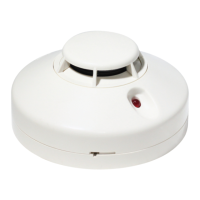
General Descrlptl®h
This B801RA plug-in detector base is used with System
Sensor smoke and heat detector heads. The capability of
plugging these detectors into a variety of special bases
makes them more versatile than equivalent direct-wired
models.
The B801RA base is intended for use in 4-wire systems,
with screw terminals provided for power and remote
announciator connections.
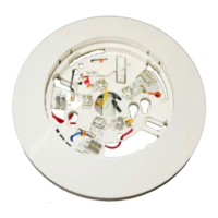
M®uh(lhg
Figure 1 shows mechanical mounting details. These
detector bases mount to typical junction boxes. Attach the
base to the box using the screws supplied with the
junction box.
F]gure 1. Termlnal Iay®ut=
156-80l-00RC