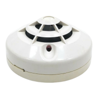
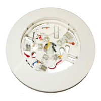
Do you have a question about the System Sensor WFD Series and is the answer not in the manual?
Electrical specifications for device contacts.
Minimum flow rate required for detector activation.
Static pressure and operating temperature ranges.
Dimensions, pipe compatibility, and enclosure rating.
Crucial information for safe and proper installation and use.
How vane-type detectors work based on water flow.
Recommendations for mounting location to ensure proper function.
Procedure for drilling and preparing the pipe for installation.
Steps to secure the detector to the pipe using U-bolts.
Verifying the installation for leaks before system activation.
Details on the SPDT switches and wiring options.
How to set the pneumatic delay to prevent false alarms.
Procedure to verify the detector's activation and delay function.
Steps to prevent water damage and ensure safety during maintenance.
Conditions or issues that may prevent proper detector operation.
Manufacturer's warranty terms and conditions.
Electrical contact ratings and activation flow rate.
Physical size and operating temperature limits.
Types of pipe tees the detector is designed for.
Instructions for purchasers and installers on manual use.
How water flow deflects the vane to produce an output.
Relevant NFPA standards and local codes for installation.
Choosing and attaching the correct paddle to the actuator.
Checking switch contacts with an ohmmeter before system use.
Wiring for FACP connection and local bell.
Modifying the delay mechanism for optimal performance.
Verifying detector reaction to test valve operation.
Information on replacing faulty delay or switch enclosure components.
Electrical contact ratings and activation flow rate.
Overall dimensions and shipping weight.
Tee depth requirements for various pipe types.
Instructions for purchasers and installers on manual use.
How water flow activates the detector's switched output.
Adherence to NFPA standards for alarm device installation.
Procedure for threading the detector into the appropriate tee fitting.
Verifying switch function using an ohmmeter before system use.
Wiring instructions for connecting to fire alarm control panels.
Procedure for ordering and replacing damaged paddle components.
Electrical contact ratings and physical dimensions of the switch.
Specifications for valve stem engagement and mounting.
Instructions for installation and operation of supervisory switches.
Avoiding upward actuator mounting to prevent water ingress.
Recommendations for bolt positioning on narrow valve yokes.
Instructions for using J-bolts on valves with limited space.
Steps for adjusting the valve stem for switch engagement.
Examples of correct and incorrect mounting positions for the switch.
Procedure to test switch function during valve operation.
Electrical contact ratings and physical size of the switch.
Maximum stem extension and shipping weight.
Instructions for installation and operation of supervisory switches.
How the actuating lever engages the valve's target or flag.
Types of post indicator valve installations and switch setup.
Procedure for installing the switch on butterfly valve gear housings.
Adjusting the actuating arm for proper travel and clearance.
How to reverse the switch action by repositioning the enclosure.
Electrical contact ratings and physical size of the tamper switch.
How the switch detects cover removal and resets.
Adherence to NFPA standards for alarm device installation.
Procedure for mounting the cover tamper switch bracket and switch.
Wiring diagrams for connecting the tamper switch to FACP.
Checking that the circuit resets correctly after cover replacement.
Electrical contact ratings and operating temperature range.
How the switch monitors removal of the pressure switch cover.
Instructions for routing wires from the tamper switch mechanism.
Electrical contact ratings and physical size of the pressure switch.
Maximum service pressure and operating temperature range.
How diaphragm movement actuates snap action switches.
Guidelines for mounting the pressure switch in various positions.
Adjusting pressure switch settings for desired alarm points.
Procedure for adjusting EPS40-1 and EPS120-1 settings.
Adjusting EPS40-2 and EPS120-2 pressure windows and settings.
Electrical contact ratings and adjustment ranges.
Operating temperature range and enclosure ratings.
Instructions for purchasers and installers on manual use.
How diaphragm movement triggers switch actuation.
Guidelines for mounting the switch where vibration is minimal.
Adjusting factory settings for fall and rise pressure points.
Procedure for adjusting EPS40-1 and EPS120-1 settings.
Adjusting EPS40-2 and EPS120-2 pressure windows and settings.
Operating voltage and average current for SSM and SSV bells.
Sound output in decibels (dBA) for different models.
Recommendations for installing bells per NFPA and local codes.
Intended use of bells and SSM series polarization for wiring supervision.
NFPA standards and local codes applicable to alarm devices.
Requirement for continuous power from the alarm system or panel.
Steps for mounting the bell mechanism to an electrical box.
How sound output is measured according to UL Standard 464.
Conditions that may affect the loudness or hearing of the alarm bell.
Manufacturer's warranty terms for SSM and SSV bell series.
| Brand | System Sensor |
|---|---|
| Model | WFD Series |
| Category | Security Sensors |
| Language | English |


 Loading...