N770-06-00 1 I56-509-01
WFDTNR Vane-type
Waterflow Detector
INSTALLATION AND MAINTENANCE INSTRUCTIONS
A Division of Pittway
3825 Ohio Avenue, St. Charles, Illinois 60174
1-800-SENSOR2, FAX: 630-377-6495
Important
Please Read Carefully And Save
This instruction manual contains important information
about the installation and operation of waterflow detectors.
Purchasers who install waterflow detectors for use by oth-
ers must leave this manual or a copy of it with the user.
Read all instructions carefully before beginning.
CAUTION
Use vane-type waterflow detectors in wet-pipe systems
only. DO NOT USE IN DRY-PIPE, DELUGE, OR PRE-AC-
TION SYSTEMS. The sudden inrush of water in such sys-
tems may break the vane off or damage the mechanism. Do
not use in potentially explosive atmospheres. Do not leave
unused wires exposed.
Principles Of Operation
Vane-type waterflow detectors mount to wet-pipe systems
only. Water flow in the pipe deflects a vane. Deflection of
the vane produces a switched output. All detectors will ac-
tivate on a sustained flow of water greater than 10 gallons
per minute (gpm) but will not activate if the flow rate is
less than 4 gpm.
Compatible Pipe Tees
Model WFDTNR fits 1"–1
1
/2" NPT threaded ferrous and
brass, 1" - 2" sweat brass, 1
1
/2" polybutylene plastic and 1"
pvc plastic tees having a 1" threaded NPT branch (see Fig-
ure 1 and chart for recommended tee depths).
Installation Guidelines
Before installing any waterflow alarm device, be thor-
oughly familiar with:
NFPA 72: Installation, Maintenance and Use of Local
Protective Signalling Systems
Specifications
Contact Ratings: 10 A @ 125/250 VAC
2.5 A @ 24 VDC
Triggering Threshold Bandwidth (Flow Rate): 4 - 10 GPM
Static Pressure Rating: 250 PSI (Max.)
Overall Dimensions, Installed: 3.25" x 4.25" cover dia.
3.25" above pipe tee
Operating Temperature Range: 32°F - 120°F (0°C - 49°C)
Shipping Weight: 1.5 lbs.
NFPA 13: Installation of Sprinkler Systems, specifically
Section 3.17
NFPA 25: Inspection, Testing and Maintenance of Sprin-
kler Systems, specifically Chapters 4 and 5
NFPA 13D: Standard for Residential Dwellings
NFPA 13R: Standard for Multifamily Dwellings
Other applicable NFPA standards, local codes and the re-
quirements of the authority having jurisdiction.
Failure to follow these directions may result in failure of the
device to report a waterflow condition. System Sensor is
A78-2110-00
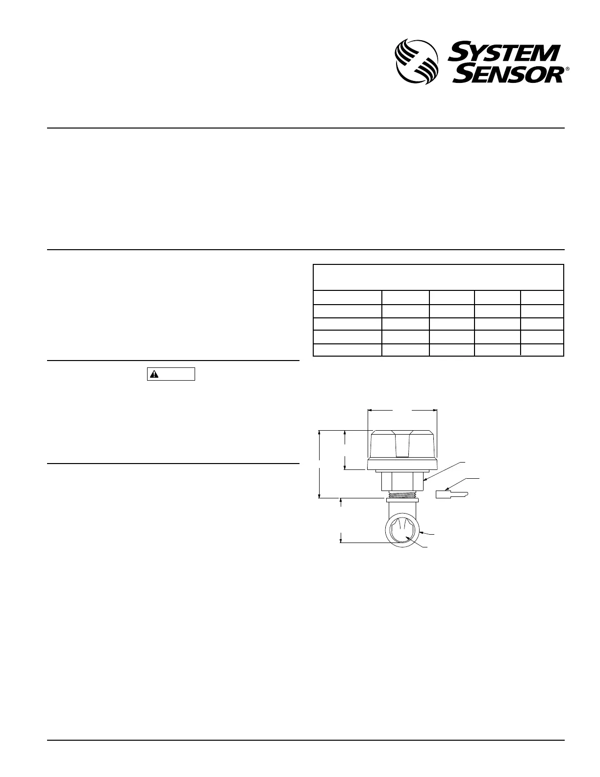
Figure 1. Mounting dimensions:
3 1/4"
1 3/4"
3 1/4"
HEX TEE ADAPTOR
INSTALLATION GAGE
(END OF PADDLE TREE)
MUST FIT BETWEEN TOP
OF TEE AND BOTTOM OF
HEX TEE ADAPTOR FLANGE.
PIPE TEE FITTING
PLASTIC VANE
"TEE DEPTH"
REFER TO
TEE DEPTH
TABLE
Approximate Tee Depth Requirements
(See Figure 1)
Tee Depth Threaded Sweat Poly B CPVC
1 × 1 × 1″
1
1
/
4
× 1
1
/
4
× 1″
1
1
/
2
× 1
1
/
2
× 1″
2 × 2 × 1"
2
1
/
8
″
2
1
/
2
″
2
3
/
4
″
N/A 2
3
/
4
″
2
1
/
4
″
2
1
/
6
″ N/A
2
1
/
2
″
N/AN/A
N/A
N/A
1
3
/
4
″ N/A 2
1
/
4
″
Technical Manuals Online! - http://www.tech-man.com