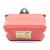
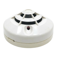
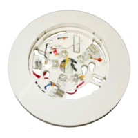
Top View
Switch 1
COM
COM
ABBA
Switch 2
NOTE: Common and B connections will
close when vane is deflected, i.e.,
when water is flowing. Dual switches
permit applications to be combined
on a single detector.
COM
COM
COM
COM
Typical FACP Connection
B
COM
Typical Local Bell Connection
Break wire as shown for
supervision of connection.
DO NOT allow stripped wire
leads to extend beyond
switch housing. Do NOT
loop wires.
end-of-line resistor
to nonsilenceable initiating
zone of listed FACP
to power source
compatible
with bell
local
bell
CONTACT RATINGS
125/250 VAC
24 VDC
10 AMPS
2.5 AMPS
B
B
B
B
WFD
WFD
WFD Switch
Assembly
(Multiple Detectors)
A78-1586-00
Figure 4. WFD wiring:
GROUND
SCREW
(GREEN)
MOUNTING
PLATE
Figure 5A. Ground screw location: Figure 5B. Knockout plug removal:
A78-1914-03A78-2063-00
D770-01-00 5 I56-459-07
Technical Manuals Online! - http://www.tech-man.com

 Loading...


