Do you have a question about the System Sensor WFD60 and is the answer not in the manual?
Details on contact ratings, pressure, dimensions, temperature, and pipe compatibility.
Guidance on reading the manual, user responsibilities, and general warnings.
Explains how water flow deflects a vane to activate a switch after a delay.
Rules for mounting location, orientation, and distance from fittings.
Detailed steps for preparing the pipe, drilling, and mounting the detector.
Instructions for connecting the detector to alarm systems or bells.
Checks for leaks and switch functionality before system activation.
How to adjust the pneumatic delay mechanism to prevent false alarms.
Procedure to test the detector's response to water flow using a test valve.
Guidelines for inspecting for leaks, testing, and replacing faulty components.
Explains conditions where detectors may not work or require specific system configurations.
Details the warranty period, coverage, and claims process for the product.
Contact ratings, flow rates, pressure, dimensions, and temperature for WFDT/WFDTH.
Advice on reading the manual and user responsibilities for installation.
Explains vane deflection and switch activation based on water flow.
Requirements for familiarization with NFPA standards before installation.
Steps to check for leaks and verify switch operation before system activation.
Wiring instructions for connecting to fire alarm control panels and local bells.
Procedure to adjust the pneumatic delay mechanism to prevent false alarms.
Instructions for inspecting, testing, and replacing components.
Conditions affecting operation, communication issues, and valve requirements.
Details the warranty coverage, limitations, and claim procedures for the product.
Contact ratings, flow rates, pressure, dimensions, and temperature for WFDTNR.
Advice on reading the manual and user responsibilities for installation.
Explains vane deflection and switch activation based on water flow.
Requirements for familiarization with NFPA standards before installation.
Steps to check for leaks and verify switch operation before system activation.
Wiring instructions for connecting to fire alarm control panels.
Instructions for inspecting, testing, and replacing components.
Conditions affecting operation, communication issues, and valve requirements.
Details the warranty coverage, limitations, and claim procedures for the product.
Contact ratings, dimensions, stem extensions, temperature, and weight.
Rules for mounting position, yoke clearance, and limited clearance valves.
Detailed steps for mounting the switch on gate valves, including stem grooving.
How to test the supervisory switch operation by moving the valve handle.
Limitations related to communication, service life, and insurance.
Details the warranty coverage, limitations, and claim procedures for the product.
Contact ratings, dimensions, temperature, and weight for PIBV2 switches.
How the PIBV2 engages valve targets and its adjustable lever feature.
Steps for installing on rising or falling flag post indicator valves.
Steps for installing the PIBV2 on butterfly valves.
How to reverse the switch's action for different valve types or orientations.
Limitations related to communication, service life, and insurance.
Details the warranty coverage, limitations, and claim procedures for the product.
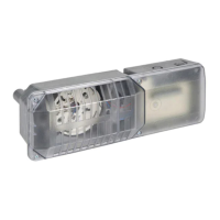
Contact ratings, dimensions, temperature, and shipping weight for the tamper switch.
Mounts to terminal blocks to detect cover removal, providing a switch output.
Requirements for familiarization with NFPA standards before installation.
Attaching the switch and bracket to the terminal block.
Wiring instructions for connecting the tamper switch to alarm panels or bells.
Details the warranty coverage, limitations, and claim procedures for the product.
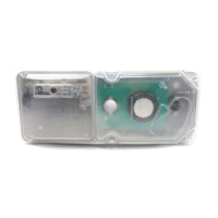
Contact ratings, temperature range, and shipping weight for the 546-8000 switch.
Mounts to pressure switches to monitor cover removal, providing a switch output.
Instructions for wiring the switch as shown in diagrams for different circuit types.
Details the warranty coverage, limitations, and claim procedures for the product.
Contact ratings, dimensions, temperature, service pressure, and adjustment range.
Explains how diaphragm movement actuates switches based on pressure changes.
Instructions for removing the cover and mounting the switch securely.
How to adjust the pressure set points for alarm and reset using the main adjustment wheel.
Details the warranty coverage, limitations, and claim procedures for the product.
Contact ratings, dimensions, temperature, service pressure, and adjustment ranges.
Explains how diaphragm movement actuates switches based on pressure changes.
Instructions for mounting the switch in upright, horizontal, or side positions.
How to adjust pressure windows and set points for single and dual-switch models.
Details the warranty coverage, limitations, and claim procedures for the product.
Voltage, current, temperature, and sound output for SSM and SSV bells.
Information on NFPA standards, intended use, and polarity for supervision.
Steps for removing the gong, wiring, mounting, and replacing the gong.
Limitations regarding power, water flow, communication, and audibility.
Details the warranty coverage, limitations, and claim procedures for the product.
| Tamper Switch | Yes |
|---|---|
| Alarm Current | 0.04 A |
| Current Draw (standby) | 0.04 A |
| Current Draw (alarm) | 60 mA |
| Contact Ratings | 2.0 A @ 30 VDC |
| Operating Temperature Range | 32°F to 120°F (0°C to 49°C) |
| Operating Humidity Range | 10% to 93% (non-condensing) |
| Mounting | Surface mount |
| Compatibility | Compatible with fire alarm control panels |