D770-08-00 2 I56-551-02
a. Mount the device directly to the line via the 1/2" NPT
pressure connection. The use of teflon pipe sealant
tape is recommended. Be sure the fitting is tight
enough to prevent leaks.
b. Apply tightening torque to the black plastic hex por-
tion of device.
CAUTION
High voltage. Electrocution hazard. Do not handle live AC
wiring or work on a device to which AC power is applied.
Doing so may result in severe injury or death.
3. Wire the device in accordance with the National Electri-
cal Code. Two 7/8" diameter conduit connection holes
have been provided in the mounting plate to accept stan-
dard 1/2" conduit fittings (one is removable knock-out
type). If a NEMA 4/UL 4x (waterproof unit) is required,
waterproof flexible metallic conduit and appropriate
conduit fittings must be used. Recommended connectors
are Thomas and Betts PN 5332 (180° coupling), PN 5352
(90° coupling), and PN 5262 seal ring.
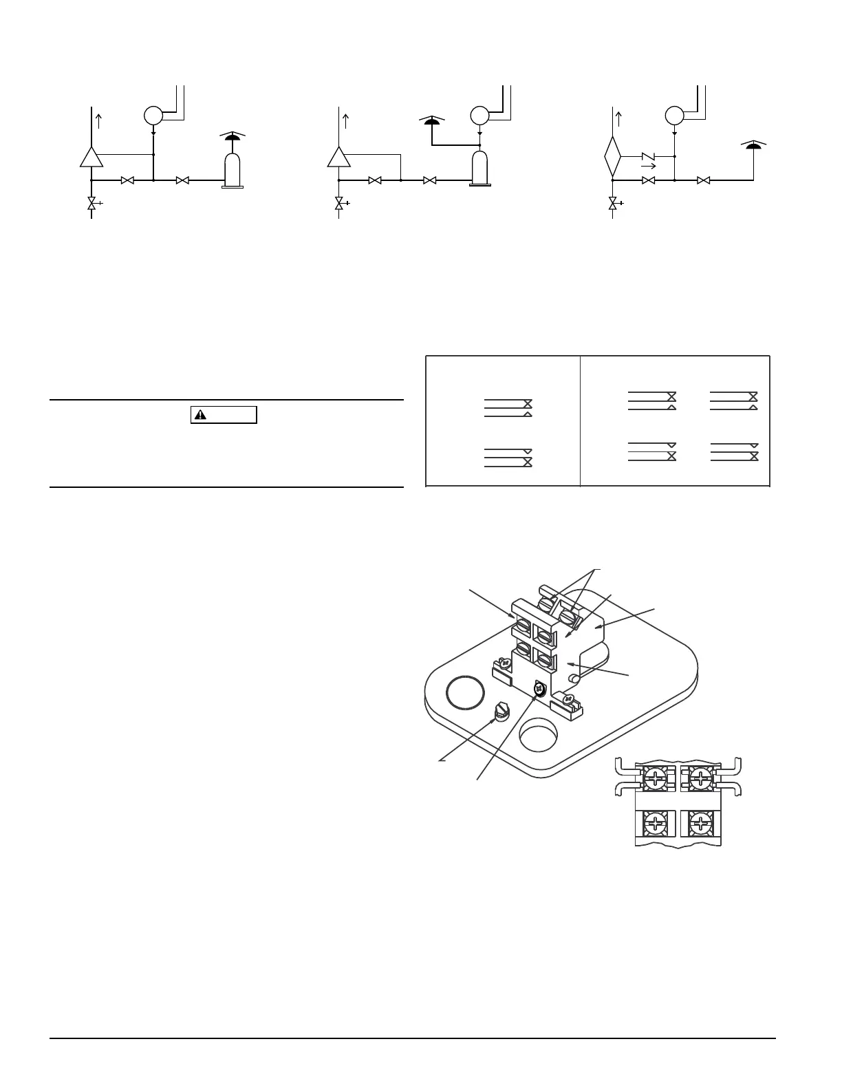
4. Connect wiring to terminals (see Figure 3 and Table 1).
WET
SYSTEM
ALARM
CHECK
VALVE
OS & Y
VALVE
WATER
BY-PASS
VALVE
LOCAL ALARM
SHUT OFF
VALVE
RETARD
WATER
MOTOR
GONG
EPS10
WET
SYSTEM
ALARM
CHECK
VALVE
OS & Y
VALVE
WATER
BY-PASS
VALVE
LOCAL ALARM
SHUT OFF
VALVE
RETARD
WATER
MOTOR
GONG
EPS10
DRY
SYSTEM
ALARM
CHECK
VALVE
OS & Y
VALVE
WATER
BY-PASS
VALVE
LOCAL ALARM
SHUT OFF
VALVE
WATER
MOTOR
GONG
CHECK
VALVE
EPS10
WET SYSTEM WET SYSTEM DRY SYSTEM
WIRE TO ALARM
INDICATING CIRCUIT
OF FIRE ALARM
CONTROL PANEL
WIRE TO ALARM
INDICATING CIRCUIT
OF FIRE ALARM
CONTROL PANEL
WIRE TO ALARM
INDICATING CIRCUIT
OF FIRE ALARM
CONTROL PANEL
TO
SPRINKLER
SYSTEM
TO
SPRINKLER
SYSTEM
TO
SPRINKLER
SYSTEM
Figure 2. Typical piping diagram for EPS10-1, EPS10-2
A78-2398-00
Figure 3. Switch terminals:
A78-2346-00
Table 1. Electrical connections (referenced at factory
settings):
MODEL EPS10-1
MODEL EPS10-2
A
COM
B
SWITCHES AT 0 P.S.I.
SWITCH AT 0 P.S.I.
SWITCH AT 4-8 P.S.I. (HIGH TRIP PT.)
B
COM
A
B
COM
A
B
COM
A
A
COM
B
A
COM
B
SWITCH 1 BOTH SWITCHES ACTIVATE SIMULTANEOUSLY
SW1 SW2
SW1 SW2
SWITCHES AT 4-8 P.S.I. (HIGH TRIP PT.)
GROUND
SCREW
COM
B
A
COMMON
TERMINALS
BREAK WIRE AS SHOWN FOR
SUPERVISION OF CONNECTION.
DO NOT ALLOW STRIPPED WIRE
LEADS TO EXTEND BEYOND
SWITCH HOUSING. DO NOT
LOOP WIRES.
SWITCH #1
SWITCH #2
SWITCH #2
LOCKING
SCREW
TERMINAL “A”
TERMINAL “B”
Technical Manuals Online! - http://www.tech-man.com