N770-05-00 1 I56-480-03
WFDT/WFDTH Vane-type
Waterflow Detectors
INSTALLATION AND MAINTENANCE INSTRUCTIONS
A Division of Pittway
3825 Ohio Avenue, St. Charles, Illinois 60174
1-800-SENSOR2, FAX: 630-377-6495
Specifications
Contact Ratings: Two sets of SPDT (Form C)
10 A @ 125/250 VAC; 2.5 A @ 24 VDC
Triggering Threshold Bandwidth (Flow Rate): 4 - 10 GPM
Service Pressure Rating: 250 PSI (Max.)
Overall Dimensions, Installed: WFDT– 4
5
/16
″
H × 3
3
/4
″
W × 6
3
/4
″
D
WFDTH– 4
5
/16
″
H × 3
9
/16
″
W × 6
3
/4
″
D
Operating Temperature Ranges: 32°F - 120°F (0°C - 49°C)
Shipping Weight: 2.6 lbs.
The WFDT is U.L. listed for indoor and outdoor installations
The WFDTH is U.L. listed for indoor use only. The WFDTH can be installed between 2×4 stud wall construction.
Important
Please Read Carefully And Save
This instruction manual contains important information
about the installation and operation of waterflow detectors.
Purchasers who install waterflow detectors for use by
others must leave this manual or a copy of it with the user.
Read all instructions carefully before beginning.
CAUTION
Use vane-type waterflow detectors in wet-pipe systems
only. DO NOT USE IN DRY-PIPE, DELUGE, OR PRE-AC-
TION SYSTEMS. The sudden inrush of water in such sys-
tems may break the vane off or damage the mechanism. Do
not use in potentially explosive atmospheres. Do not leave
unused wires exposed.
Principles Of Operation
Vane-type waterflow detectors mount to water filled pipes
in sprinkler systems. Water flow in the pipe deflects a vane.
Deflection of the vane produces a switched output, usually
after a specified delay.
All WFDTs have a pneumatically controlled mechanical
delay mechanism. Delays are noncumulative; they reset if
the flow of water stops before the entire delay has elapsed.
All detectors will activate on a sustained flow of water
greater than 10 gallons per minute (gpm) but will not
activate if the flow rate is less than 4 gpm.
Compatible Pipe Tees
The WFDT and WFDTH fit 1
″
to 1
1
/2
″
NPT threaded ferrous
and brass, 1
″
to 2
″
sweat brass, 1
1
/2
″
polybutylene plastic
and 1
″
pvc plastic tees having a 1
″
threaded NPT branch
(see Figure 1 and chart for recommended tee depths).
Installation Guidelines
Before installing any waterflow alarm device, be
thoroughly familiar with:
NFPA 72: National Fire Alarm Code
NFPA 13: Installation of Sprinkler Systems
NFPA 25: Inspection, Testing, and Maintenance of
Water-based Fire Protection Systems
NFPA 13D: Standard for 1 and 2 Family Dwellings and
Manufactured Homes
NFPA 13R: Standard for Multi-family Dwellings
Approximate Tee Depth Requirements
(See Figure 1)
Tee Depth Threaded Sweat Poly B CPVC
1 × 1 × 1″
1
1
/
4
× 1
1
/
4
× 1″
1
1
/
2
× 1
1
/
2
× 1″
2 × 2 × 1"
2
1
/
8
″
2
1
/
2
″
2
3
/
4
″
N/A 2
3
/
4
″
2
1
/
4
″
2
1
/
6
″ N/A
2
1
/
2
″
N/AN/A
N/A
N/A
1
3
/
4
″ N/A 2
1
/
4
″
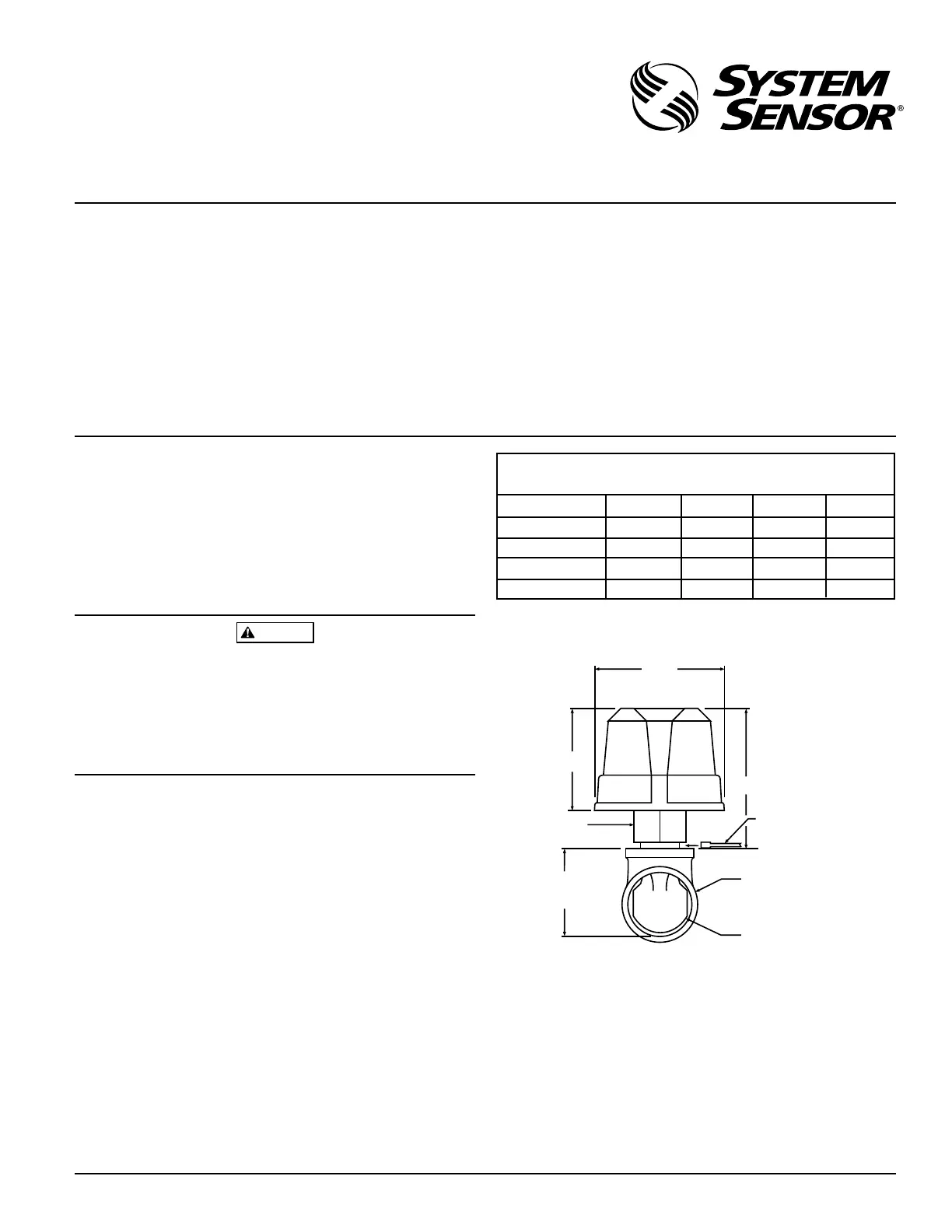
Figure 1. Mounting dimensions:
3
3
/
4
″
(WFDT)
3
9
/
16
″
(WFDTH)
3″
4
5
/
16
″
Gage (End of Paddle Tree)
Must Fit Between Top of
Tee and Bottom of Flange
Tee Fitting
Plastic Vane
Tee Adapter
Tee Depth
Refer to
Tee Depth
Table
A78-1939-00
Technical Manuals Online! - http://www.tech-man.com