D770-01-00 6 I56-459-07
4
0
1
23
15
30
5
45
55
70
Dial setting
Seconds (±50%)
0
1
2
3
4
5
3
2
0
1
4
5
15
30
45
55
70
ON
NU
MB
ER
DIAL
TIME
APP
ROX
IMA
TE
DEL
AY
(SE
CON
DS)
Table of dial settings
embossed here.
See below.
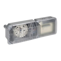
Delay adjustment dial
0
0
A78-1496-05
Figure 6. Delay adjustment dial:
Mechanical Delay Adjustment
The pneumatic delay is preset at the factory to dial setting
2. To adjust the setting, turn the adjustment dial clockwise
to increase the delay, counterclockwise to decrease it. The
delay is adjustable from 0 to 70 seconds. See Figure 6.
NOTE: Set the delay to the minimum required to prevent
false alarms from flow surges.
After extended service, parts of the detector may become
worn, reducing the delay time and causing false alarms. If
this happens, increase the delay. If the delay is already at
the maximum, replace the mechanical delay assembly. Re-
fer to Maintenance for ordering replacement parts.
Operational Testing
Always notify a central station monitoring waterflow
alarms before repairing, maintaining, or testing waterflow
alarm devices.
1. Replace the cover and tighten the tamper proof screws
with the tamper proof wrench. Store the wrench in a se-
cure place.
2. Open the inspector’s test valve and time how long it
takes for the detector to indicate a flow condition. The
detector should remain activated until the inspector’s
test valve is closed. Air pockets in the sprinkler system
may increase the apparent delay.
Maintenance
To prevent accidental water damage, control valves
should be shut tight and the system completely drained
before waterflow detectors are removed or replaced.
Inspect detectors monthly for leaks and replace if a leak
occurs. Test detectors at least monthly, as described under
Operational Testing, to ensure proper operation. Test more
often if required by the authority having jurisdiction.
Under normal conditions, System Sensor waterflow detec-
tors should provide years of trouble-free service. However,
if the delay mechanism or switch enclosure becomes
faulty, replace it. To replace the delay mechanism or
switch enclosure, use a phillips head screwdriver to re-
move the three screws that hold it in place. Either mecha-
nism can be easily replaced without removing the
detector from the pipe or draining the pipe. Do not repair
or replace any other waterflow detector components. If
any other part of the detector does not perform properly,
replace the entire detector. Failure to to follow this in-
struction may result in failure of the detector to report the
flow of water. To replace the delay mechanism, request
Part No. A3008-00. For switch enclosure, request Part No.
A77-01-02.
Technical Manuals Online! - http://www.tech-man.com