D400-73-00 2 I56-2294-03R
Electrical
Voltage: 10.2 to 32 VDC (BEAM1224)
15 to 32 VDC (BEAM1224S)
Maximum Ripple Voltage: 6.0 volts (Peak-to-peak)
Note: ripple must not fall below minimum operating voltage specification
Current (24 VDC): Avg. Standby: 17mA Max.
Avg. Alarm: 38.5mA Max.
Avg. Trouble: 8.5mA Max.
Avg. Alignment: 28mA Max.
Current (Test Mode)
(BEAM1224S only): Peak Test: 500mA Max.
Relay Contacts: 0.5A at 30 VDC
Reset Time: 0.3 Seconds Max.
Start-up Time (after 2 min. reset): 60 sec. Max.
Alarm Verification Time: 5 sec. Max.
Remote Output: Voltage: 15 to 32 VDC
(Alarm & Trouble) Note: Output voltage same as device input voltage.
Current: 15mA maximum
6mA minimum
Note: Output current is limited by 2.2Kohm resistor
Before Installing
Please thoroughly read this manual and applicable sections
of System Sensor’s Projected Beam Detector Application
Guide. Copies of this manual are available from System
Sensor.
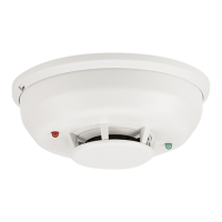
General Description
System Sensor Model BEAM1224/BEAM1224S is a long
range projected beam smoke detector designed to pro-
vide open area protection. It is to be used with UL-listed,
separately supplied power (4-wire) control panels only.
The detector consists of a transmitter/receiver unit and a
reflector. Smoke entering the area between the transmitter/
receiver and reflector causes a reduction in signal. When
the obscuration reaches alarm thresholds (chosen at the
transmitter/receiver unit), the detector generates an alarm
signal. Complete blockage of the beam causes a trouble
signal. Slow changes in obscuration due to a build up of
dirt or dust on the lens of the detector are compensated for
by a microcontroller that continuously monitors the signal
strength and periodically updates the alarm and trouble
thresholds. When the self-compensation circuit reaches its
limit, the detector generates a trouble signal, indicating the
need for service.
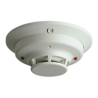
Three LEDs on the detector indicate the current status: a
red LED for alarm, a yellow LED for trouble, and a blinking
green LED for standby operation. The alarm signal latches
and can be reset by a momentary power interruption, by
using the remote reset input to the detector if using the
remote test/reset station model RTS451, or with the local
reset button located on the detector. The local reset button
is accessible by removing the outer paintable trim ring. The
yellow LED will blink in specific patterns to provide a diag-
nostic aid when diagnosing the cause of a trouble signal. It
will also blink the amount of drift compensation that has
been used at the conclusion of the test. Trouble signals
automatically reset upon removing the cause of trouble.
Red and yellow LEDs can be remotely connected to the
remote Alarm and Trouble outputs. These outputs mimic
the functions of the detector’s red and yellow LEDs. In
addition to these indicators, there is a dual digital display
that reads 00 to 99. This display is used to indicate the sig-
nal strength of the beam in alignment mode and to indicate
the sensitivity setting of the detector in percent obscuration
when setting the sensitivity of the detector. No additional
equipment is needed for alignment of the beam.
Each detector contains one Form A (normally open) con-
tact for alarm signals and one Form B (normally closed)
contact for trouble signals. The trouble contact will open
if power is removed from the detector. Thus, an additional
EOL power supervision relay is not necessary. The trouble
contacts from all the beam detectors on one initiating cir-
cuit must be connected after the last indicating device on
the loop. This prevents a single beam detector in trouble
from disabling other initiating devices on the same loop.
Special Applications
Due to the inherent capabilities of projected type beam
detectors they are often installed in locations where spot-
type detection is impractical. Projected type beam smoke
detectors are ideally suited for environmental conditions
that might include high ceilings, dusty and dirty envi-
ronments, or environments that experience temperature
extremes. Often these conditions present special problems
for the installation of spot-type detectors and even greater
problems for their proper maintenance. Due to the inherent