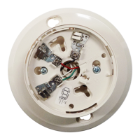
Figure 5a. Reflector Mounting Guidelines
WALL
REFLECTOR
Acceptable mounting
locations for reflector
10°
10°
C0258-00
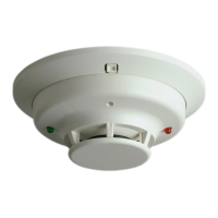
Figure 5b. Reflector Mounting Guidelines
10° maximum
optical line of sight
REFLECTOR
C0259-00
Mounting Considerations for Single Ended Beam
Detectors
There must be a permanent clear line of vision between the
detector and the reflector. Reflective objects must not be
near the line of vision between the detector and reflector.
Reflective objects too near to the line of sight can reflect
the light beam from the transmitter to the receiver. If this
occurs, the detector will not be able to distinguish these
reflections from those of the reflector and the protected
space will be compromised. Reflective objects should be
a minimum of 15 inches (38.1cm) from the line of sight
between the detector and reflector. In cases where reflective
objects cannot be avoided, the complete reflector blockage
test can be used to determine if the installation is accept-
able. See Testing and Maintenance Section of this manual.
Light sources of extreme intensity such as sunlight and hal-
ogen lamps, if directed at the receiver, can cause a dramatic
signal change resulting in fault and alarm signals. To prevent
this problem direct sunlight into the transmitter/receiver
unit should be avoided. There should be a minimum of 10°
between the pathway of the light source and detector and
the line of sight between detector and reflector.
Operation of the detector through panes of glass should
be avoided. Since single ended beam detectors operate on
a reflection principle, a pane of glass perpendicular to the
line of sight between the detector and the reflector can
reflect the light beam from the transmitter to the receiver.
If this occurs, the detector will not be able to distinguish
these reflections from those of the reflector and the pro-
tected space will be compromised.
Panes of glass will also absorb some of the light as it passes
through it. This absorption of light will reduce the acceptable
installed distance between the detector and the reflector.
In cases where operation through panes of glass cannot be
avoided some specific installation practices can help to mini-
mize the effects of the glass. These practices include: avoid
penetration of multiple panes of glass, position the glass so
that it is not perpendicular to the line of sight between the
detector and the reflector, (A minimum of 10° off perpen-
dicular should be considered), and make certain that the
glass is smooth, clear and mounted securely. The complete
reflector blockage test can be used to determine if the instal-
lation is acceptable. See Testing and Maintenance Section of
this manual.
Where high ceilings (in excess of 30 feet or 9.1 meters) are
present additional beams may be required to detect smoke at
lower levels. See System Sensor’s Projected Beam Detector
Applications Guide for further explanation.
Wiring Installation Guidelines
Always install all wiring in compliance with the National
Electrical Code, and/or the applicable local codes, and any
special requirements of the local authority having jurisdiction.
Proper wire gauges and suitable means for strain relief should
be used. The conductors used to connect beam smoke detec-
tors to control panels and accessory devices should be color-
coded to reduce the likelihood of wiring errors. Improper
connections can prevent a system from responding properly
in the event of a fire.
Installation wire used for the beam detector shall be no smaller
than 22 AWG (1.0 mm
2
). For best system performance, all wir-
ing should be twisted pair and installed in separate grounded
conduit. Do NOT mix fire system wiring in the same conduit
as any other electrical wiring. Shielded cable may be used to
provide additional protection against electrical interference.
When installing the beam smoke detector in applications
where the head unit will be mounted to either a wall or the
ceiling using the multi-mount kit (BEAMMMK) flexible con-
duit will be used. The surface mount kit (BEAMSMK) and
multi-mount kit (BEAMMMK) must be installed with the
cable before wring the unit, according to the instructions sup-
plied with the kit.
When the detector has been mounted over a recessed junction
box, all wiring should be routed out of the box and behind
the detector to the bottom of the detector where the terminal
blocks are located. When installing the wiring in the junction
D400-73-00 6 I56-2294-03R