7 I56-3102-003
7/8/2019
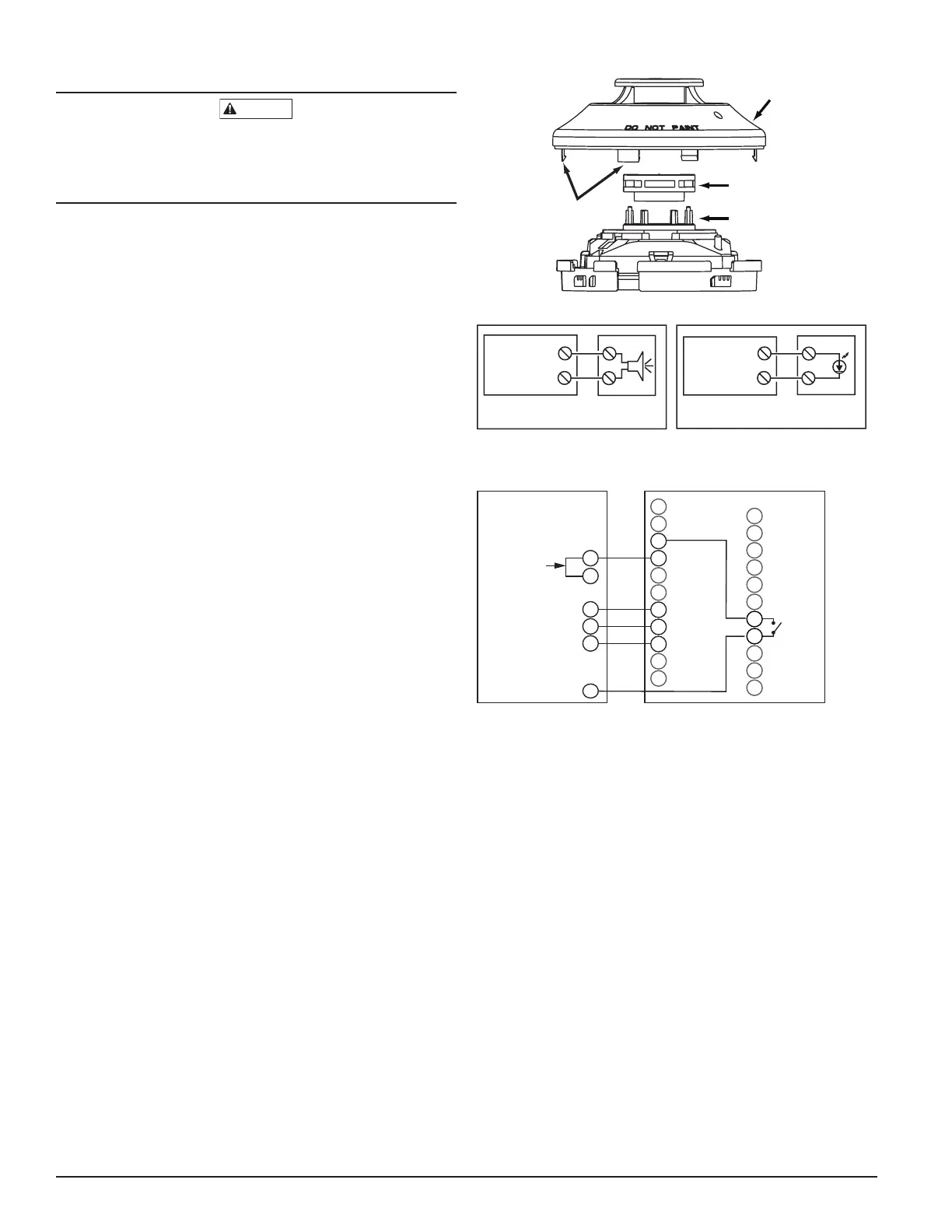
FIGURE 10. DETECTOR SENSOR EXPLODED VIEW
COVER
SENSING
CHAMBER
COVER AND
SCREEN
SENSOR
CHAMBER
COVER
REMOVAL
TABS
H0584-00
FIGURE 11. WIRING DIAGRAMS FOR OPTIONAL ACCESSORIES
ALARM
AUX OUT –
15
20
(+)
(–)
ALARM
AUX OUT –
15
20
(+)
(–)
RED
MHR/MHW
(OPTIONAL) AUDIO
ALERT
D4120A
DUCT DETECTOR
D4120A
DUCT DETECTOR
RA400ZA(OPTIONAL)
REMOTE (LED)
ANNUNCIATOR
H0554-00CDN
FIGURE 13. WIRING DIAGRAM FOR D4120A TO RTS451/RTS-
451KEYA
10
9
19
20
1
12
15
2
6
1
5
4
3
D4120A
RTS451/RTS451KEYA
(GREEN LED)
POWER
(RED LED)
ALARM
FIELD
INSTALLED
JUMPER
11
2
+
–
AUX OUT +
AUX OUT –
ALARM
R TEST
ACC +
ACC –
R RESET
7
18
8
17
6
16
14
3
13
5
4
SUP, NO
SUP, C
FOR RTS451KEYA ONLY WITHOUT A CONTROL PANEL
H0582-00CDN
alarm. Refer to the manufacturer’s published instructions for proper use of
the canned smoke agent.
Canned aerosol simulated smoke (canned smoke agent) formulas will vary
by manufacturer. Misuse or overuse to these products may have long term
adverse effects on the smoke detector. Consult the canned smoke agent man-
ufacturer’s published instructions for any further warnings or caution state-
ments.
[12.6] INSTALL THE COVER
Install the covers making sure that the cover fits into the base groove. Tighten
the seven screws that are captured in the covers.
[13] DETECTOR CLEANING PROCEDURES
Notify the proper authorities that the smoke detector system is undergoing
maintenance, and that the system will temporarily be out of service. Disable
the zone or system undergoing maintenance to prevent unwanted alarms
and possible dispatch of the fire department.
[13.1] DETECTOR SENSOR
1. Remove the sensor to be cleaned from the system.
2. Remove the sensor cover by pulling outward on each of the four re-
moval tabs that hold the cover in place. See Figure 10.
3. Vacuum the screen carefully without removing it. If further cleaning is
required continue with Step 4, otherwise skip to Step 7.
4. Remove the chamber cover/screen assembly by pulling it straight out.
5. Use a vacuum cleaner or compressed air to remove dust and debris
from the sensing chamber.
6. Reinstall the chamber cover/screen assembly by sliding the edge over
the sensing chamber. Turn until it is firmly in place.
7. Replace the cover using the holes for the LEDs for alignment and then
gently pushing it until it locks into place.
8. Reinstall the detector.
[13.2] REINSTALLATION
1. Reinstall the detector in its housing.
2. Restore system power.
3. Perform Detector Check, Section 12.3.
4. Notify the proper authorities testing has been completed and the smoke
detector system is back in operation.
[14] SENSOR REPLACEMENT (PART NO. 2D51A)
1. Remove the sensor head by rotating counterclockwise.
2. Pull gently to remove it.
3. To replace the sensor head, align the mounting features and rotate
clockwise into place.
[15] OPTIONAL ACCESSORIES
[15.1] RTS451/RTS451KEY REMOTE TEST STATION
The RTS451/RTS451KEYA Remote Test Station facilitates test of the alarm
capability of the duct smoke detector as indicated in the RTS451/RTS-
451KEYA manual. The D4120A duct smoke detector can be reset by the
RTS451/RTS451KEYA. To install the RTS451/RTS451KEYA, connect the
device as shown in Figure 12; wire runs must be limited to 25 ohms or less
per interconnecting wire. If a system control panel is used, the panel itself
may require testing.