D200-14-00 1 I56-0084-00
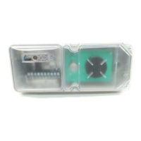
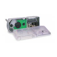
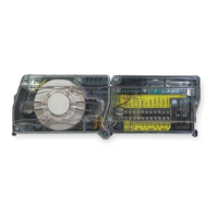
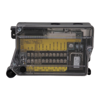
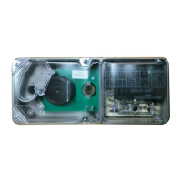
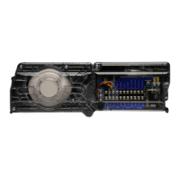
DH100ACDCLP Air Duct Smoke Detector
with Extended Air Speed Range
INSTALLATION AND MAINTENANCE INSTRUCTIONS
A Division of Pittway
3825 Ohio Avenue, St. Charles, Illinois 60174
1-800-SENSOR2, FAX: 630-377-6495
The Innovair DH100ACDCLP model is a photoelectric
detector approved for an extended air speed range of 100 to
4000 feet per minute (0.5 m/s to 20.3 m/s) and an opera-
tional temperature range of 32°F to 131°F (0°C to 55°C).
Before Installing
Please thoroughly read the System Sensor Guide for Proper
Use of Smoke Detectors in Duct Applications (I56-473),
which provides detailed information on detector spacing,
placement, zoning, wiring, and special applications. Copies
of this manual are available from System Sensor. NFPA
Standards 72 and 90A should also be referenced for detailed
information.
NOTICE: This manual shall be left with the owner/user of
this equipment.
IMPORTANT: This detector must be tested and maintained
regularly following NFPA 72 requirements. The detector
should be cleaned at least once a year.
Table of Contents Page
[1] General Description ...................................................... 1
[2] Limitations of Duct Smoke Detectors ..............................1
[3] Exploded View of Duct Smoke Detector Components......2
[4] Contents of the Duct Smoke Detector Kit........................2
[5] Installation Sequence.....................................................2
[6] Duct Smoke Detector Maintenance and Test Procedures ..5
[7] Detector Cleaning Procedures.........................................7
[8] Board Replacement........................................................8
[9] Specifications ................................................................8
Warranty ............................................................................8
[1] General Description
An HVAC system supplies conditioned air to virtually every
area of a building. Smoke introduced into this air duct sys-
tem will be distributed throughout the entire building.
Smoke detectors designed for use in air duct systems are
used to sense the presence of smoke in the duct.
Model DH100ACDCLP Air Duct Smoke Detector utilizes
photoelectric technology for the detection of smoke. This
detection method, when combined with an efficient hous-
ing design, samples air passing through the duct and allows
detection of a developing hazardous condition. When suf-
ficient smoke is sensed, an alarm signal is initiated and
appropriate action can be taken to shut off fans, blowers,
change over air handling systems, etc. These actions can
facilitate the management of toxic smoke and fire gases
throughout the areas served by the duct system.
The DH100ACDCLP detector is designed to operate on 24
VDC/VAC, 120 VAC, or 240 VAC. Alarm and supervisory
relay contacts are available for control panel interface (alarm
initiation), HVAC control, and other auxiliary functions.
Auxiliary relays are also provided for fan shut down or sig-
naling of up to 9 other detectors in the loop for multiple fan
shut down. These detectors are not designed for 2-wire
applications.
For testing, the alarm can be enabled by a magnet activated
test switch or by the optional remote test station. The duct
smoke detector latches into alarm state when an alarm
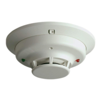
occurs. A green LED flashes to indicate power, a red LED
signals local alarm indication, and optional accessories
offer a variety of annunciation capabilities.
The DH100ACDCLP can be reset by a momentary power
interruption, the reset button on the front cover, the control
panel, or remote reset accessory. The DH100ACDCLP
incorporates a cover tamper feature that provides a trou-
ble signal after 20 minutes if the cover is removed or
improperly installed. Proper installation of the cover
removes the trouble condition.
[2] Limitations Of Duct Smoke Detectors
The National Fire Protection Association has established that
DUCT DETECTORS MUST NOT BE USED AS A SUBSTITUTE
FOR OPEN AREA DETECTOR PROTECTION as a means of
providing life safety. Nor are they a substitute for early warn-
ing in a building’s regular fire detection system.
System Sensor supports this position and strongly recom-
mends that the user read NFPA Standards 90A, 72, and 101.
The DH100ACDCLP Air Duct Smoke Detectors are listed per
UL 268A.
This device will not operate without electrical power.
Fire situations may cause an interruption of power. The
system safeguards should be discussed with your local
fire protection specialist.
This device will not sense smoke unless the ventilation
system is operating and the cover is installed.
For this detector to function properly, it MUST be installed
according to the instructions in this manual. Furthermore,
the detector MUST be operated within ALL electrical and
environmental specifications listed in this manual. Failure
to comply with these requirements may prevent the detec-
tor from activating when smoke is present in the air duct.
 Loading...