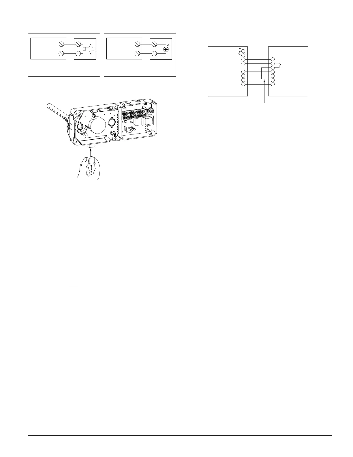
Figure 13. Testing detector alarm:
Cover
Tamper — If the cover is removed or not properly secured
for a period longer than 20 minutes, a trouble
signal is generated to indicate the cover is missing.
[6.2.2] Alarm Tests
[6.2.2.1] M02-04-00 Magnet Test
1. Place the painted surface of the magnet onto the TEST
locator on the bottom of the housing (Figure 13).
2. The red alarm LED on the detector should latch on, as
should any accessories (i.e. RA400Z, RTS451). Verify
system control panel alarm status and control panel exe-
cution of all intended auxiliary functions (i.e. fan shut-
down, damper control, etc.).
3. The detector must be reset by system control panel, front
cover reset button, or remote accessory.
[6.2.2.2] RTS451/RTS451KEY Remote Test Station
The RTS451/RTS451KEY Remote Test Station facilitates test
of the alarm capability of the duct smoke detector as indi-
cated in the RTS451/RTS451KEY manual. The DH100ACD-
CLP duct smoke detector can be reset by the
RTS451/RTS451KEY. If a system control panel is used, the
panel itself may also require testing.
To install the RTS451/RTS451KEY, connect the device as
shown in Figure 9; wire runs must be limited to 25 ohms
or less per interconnecting wire.
Please note that the magnetic coil supplied with the
RTS451 and RTS451KEY is not required when these acces-
sories are used with the DH100 Series detectors. The func-
tionality of the magnetic coil has been designed into the cir-
cuitry of the new Innovair™ duct smoke detectors.
D200-14-00 7 I56-0084-00
[6.2.2.3] SSK451 Multi-Signaling Accessory
The System Sensor SSK451 Multi-Signaling accessory com-
bines a sounder feature with a key activated test and reset
function. Green, amber and red LEDs provide a visual indica-
tion of power, trouble, and alarm respectively. An optional
strobe (PS24LO) with a smoke lens can be added to conform
to the codes of certain jurisdictions.
To install the SSK451, connect the device as shown in figure
12.
[6.2.3] Sensitivity Tests
[6.2.3.1] MOD400 or MOD400R Test
After verification of alarm capability, use the MOD400R test
module with a voltmeter to check detector sensitivity as
indicated in the test module’s manual. The housing cover
must be removed to perform this test.
If test module readings indicate that the detector head is
outside of the acceptable range that is printed on the label
of the detector, the detector chamber requires cleaning per
Section [7] of this manual.
[7] Detector Cleaning Procedures
Notify the proper authorities that the smoke detector sys-
tem is undergoing maintenance, and that the system will
temporarily be out of service. Disable the zone or system
undergoing maintenance to prevent unwanted alarms and
possible dispatch of the fire department.
[7.1] Air Filters
1. Turn off power to the system.
2. Remove and inspect sampling tube filters.
3. If filters are heavily coated with dirt, replace them with
new filters. If they are not heavily coated, use a vacuum
cleaner or compressed air nozzle to remove dust, then
reinstall the filters.
[7.2] Photo Detector Board
1. Remove the screen by gently grasping on each side and
pulling straight off.
2. Lift the photo chamber in the same fashion. Vacuum the
screen and cover. Use clean, compressed air to loosen
and blow out any remaining debris. Replacement
screens (S08-39-01) are available.
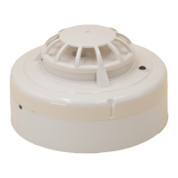
Figure 11. Wiring diagrams for optional accessories:
A78-2354-11
15 ALARM SIGNAL
3
14
2 RESET
11 TEST
20 AUX. POWER (-)
19 AUX. POWER (+)
SSK451
FIELD INSTALLED
JUMPER FOR
TEMPORAL PATTERN
SUPERVISORY
CONTACT
NO
FIELD INSTALLED
JUMPER
DH100ACDC
COMMON 3
TEMPORAL SELECT 2
ALARM SIGNAL 1
SUPERVISORY SIGNAL 4
RESET 7
TEST 8
POWER (-) 6
POWER (+) 5
Figure 12. Wiring diagram for DH100ACDCLP to
SSK451
 Loading...