Do you have a question about the System Sensor 1400 and is the answer not in the manual?
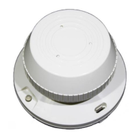
Details system voltage, ripple voltage, start-up capacitance, standby, and alarm current ratings.
How to use the detector's built-in switch to simulate an alarm condition.
Using a test module with a voltmeter to check detector sensitivity.
Using an aerosol generator to test the detector's response to simulated smoke.
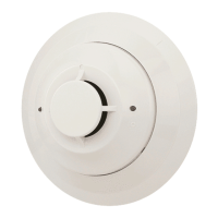
Specifies resistive/inductive load ratings for Form A and Form C contacts.
Lists voltage, current, and timing specifications for the detectors.
How to use the detector's built-in switch to simulate an alarm condition.
Using a calibrated test card to verify the detector's response without an alarm.
Using a test module with a voltmeter to check detector sensitivity.
Using an aerosol generator to test the detector's response to simulated smoke.
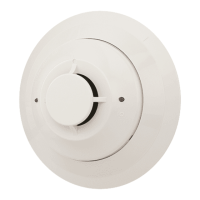
General guidance on testing methods for the 2400/2400TH detectors.
How to use the detector's built-in switch to simulate an alarm condition.
Using a calibrated test card to verify the detector's response without an alarm.
Using a test module with a voltmeter to check detector sensitivity.
Using an aerosol generator to test the detector's response to simulated smoke.
Specific test for the thermal component of the 2400TH model.
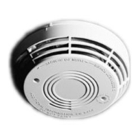
How to use the detector's built-in switch to simulate an alarm condition.
Using a calibrated test card to verify the detector's response without an alarm.
Using a test module with a voltmeter to check detector sensitivity.
Using an aerosol generator to test the detector's response to simulated smoke.
Specific test for the thermal component of the 2400AT/2400AIT models.
How to use the detector's built-in switch to simulate an alarm condition.
Using a calibrated test card to verify the detector's response without an alarm.
Using a test module with a voltmeter to check detector sensitivity.
Using an aerosol generator to test the detector's response to simulated smoke.
Specific test for the thermal component of the 2412AT/2424AT/2424AIT models.
How to use the detector's built-in switch to simulate an alarm condition.
Using a calibrated test card to verify the detector's response without an alarm.
Using a test module with a voltmeter to check detector sensitivity.
Using an aerosol generator to test the detector's response to simulated smoke.
Specific test for the thermal component of the 2412TH/2424TH models.
| Brand | System Sensor |
|---|---|
| Model | 1400 |
| Category | Smoke Alarm |
| Language | English |